MANUAL TRANSMISSION (E-W) -
Output Shaft
22A-4-4
PWEE9508
E
May 1995Mitsubishi Motors Corporation
A
E
"
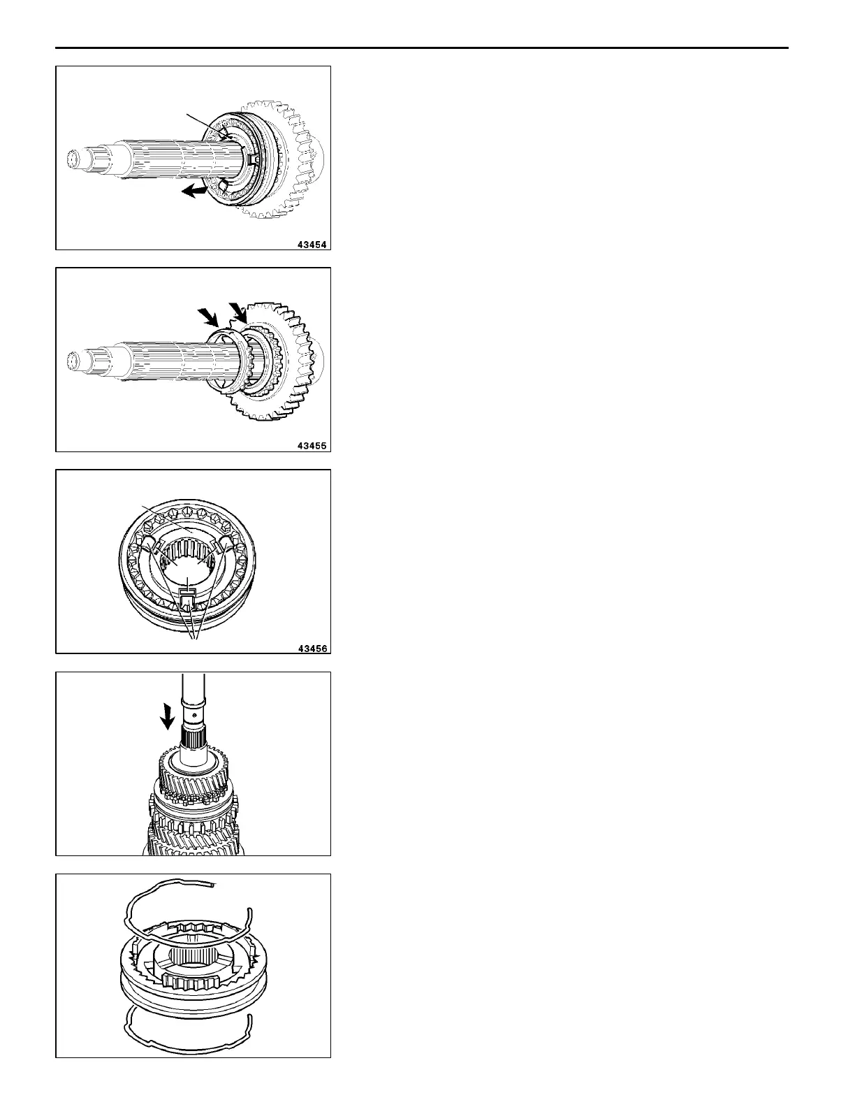
1ST - 2ND SYNCHRONIZER HUB REMOVAL
(1) Remove the snap ring 8.
(2) Take the h u b together with the synchronizer sleeve off
the shaft.
A
F
"
1ST GEAR WHEEL REMOVAL
Take the gear wheel together with the synchronizer ring off
the shaft.
A
G
"
SYNCHRONIZER SPRINGS/ROLLERS REMOVAL
(1) Press the hub 9 out of the synchronizer sleeve.
(2) Remove the rollers 10 and springs 11.
NOTE
Make sure that no parts are lost.
A
H
"
OUTPUT SHAFT FROM/GEAR WHEELS
REMOVAL
(1) Place the output shaft under a press and support the
1st gear wheel.
(2) Press the output shaft completely out of the bearing
bushes of the gear wheels.
NOTE
The bearing bush of the 1st gear wheel cannot be
disassembled.
A
I
"
SYNCHRONIZER SPRINGS REMOVAL
(1) Press the hub out of the synchronizer sleeve.
(2) Remove the two springs.
NOTE
Make sure that none of the parts are lost.
RevisedPWEE9508-BMitsubishi Motors Corporation
May 1996
E
8
9
10
11
RMT0026
RMT0027
 Loading...