F-97
FX Series PLC User's Manual - Data Communication Edition
Non-Protocol Communication (RS/RS2 Instruction)
12 Related Data
12.4 Details of Related Devices (RS2 Instruction)
A
Common Items
B
N:N Network
C
Parallel Link
D
Computer Link
E
Inverter
Communication
F
Non-Protocol
Communication
(RS/RS2 Instruction)
G
Non-Protocol
Communication
(FX
2N
-232IF)
H
Programming
Communication
I
Remote
Maintenance
Apx.
Discontinued
models
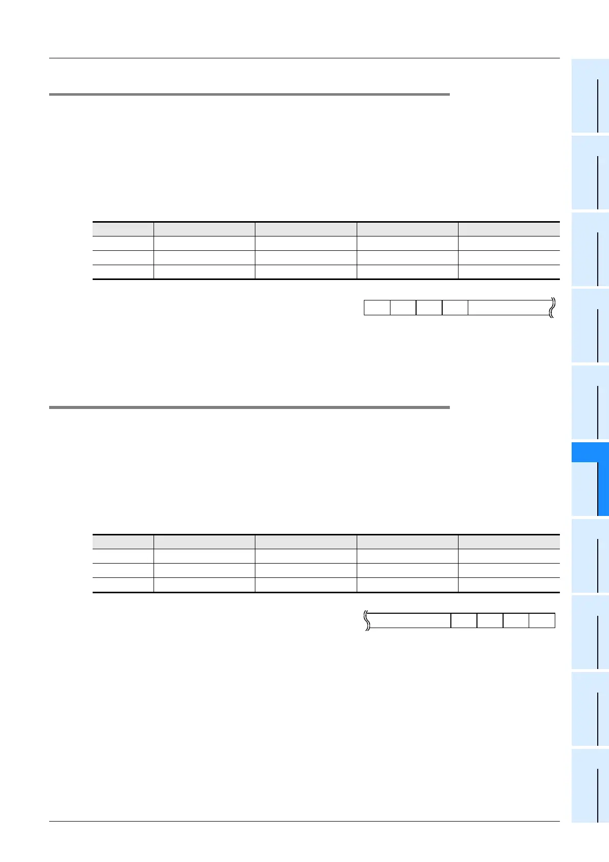
12.4.14 Header [D8380, D8381, D8410, D8411, D8430 and D8431]
These devices set the headers 1, 2, 3 and 4.
1. Detailed contents
When "header provided" is selected in the communication format setting, the headers are set in the sent and
received data.
Up to four headers can be set in each channel.
When communication port ch0 is used, D8380 and D8381 set the headers.
When communication port ch1 is used, D8410 and D8411 set the headers.
When communication port ch2 is used, D8430 and D8431 set the headers.
The headers are set in the following order.
When data is sent, the data set in the headers is added at
the head of the specified send data.
When data is received, receiving begins when the data set
in the headers is received.
2. Cautions on use
Even if "header provided" is selected, headers are not provided if header 1 is set to "H00".
The area before "H00" (in 1-byte units) is used to set the headers.
12.4.15 Terminator [D8382, D8383, D8412, D8413, D8432 and D8433]
These devices set the terminators 1, 2, 3 and 4.
1. Detailed contents
When "terminator provided" is selected in the communication format setting, the terminators are set in the
sent and received data.
Up to four terminators can be set in each channel.
When communication port ch0 is used, D8382 and D8383 set the terminators.
When communication port ch1 is used, D8412 and D8413 set the terminators.
When communication port ch2 is used, D8432 and D8433 set the terminators.
The terminators are set in the following order.
When data is sent, the data set in the terminators is added
at the end of the specified send data.
When data is received, receiving is completed when the
data set in the terminators is received.
2. Cautions on use
Even if "terminator provided" is selected, terminators are not provided if terminator 1 is set to "H00".
The area before "H00" (in 1-byte units) is used to set the terminators.
Header Header 1 Header 2 Header 3 Header 4
ch0
D8380 (lowest-order byte) D8380 (highest-order byte) D8381 (lowest-order byte) D8381 (highest-order byte)
ch1
D8410 (lowest-order byte) D8410 (highest-order byte) D8411 (lowest-order byte) D8411 (highest-order byte)
ch2
D8430 (lowest-order byte) D8430 (highest-order byte D8431 (lowest-order byte) D8431 (highest-order byte)
Terminator Terminator 1 Terminator 2 Terminator 3 Terminator 4
ch0
D8382 (lowest-order byte) D8382(highest-order byte) D8383 (lowest-order byte) D8383 (highest-order byte)
ch1
D8412 (lowest-order byte) D8412(highest-order byte) D8413 (lowest-order byte) D8413 (highest-order byte)
ch2
D8432 (lowest-order byte) D8432 (highest-order byte) D8433 (lowest-order byte) D8433 (highest-order byte)
1 2 3 4Data
Header
1 2 3 4Data
Terminator

 Loading...


