3-47 Names of each part
3
Controller
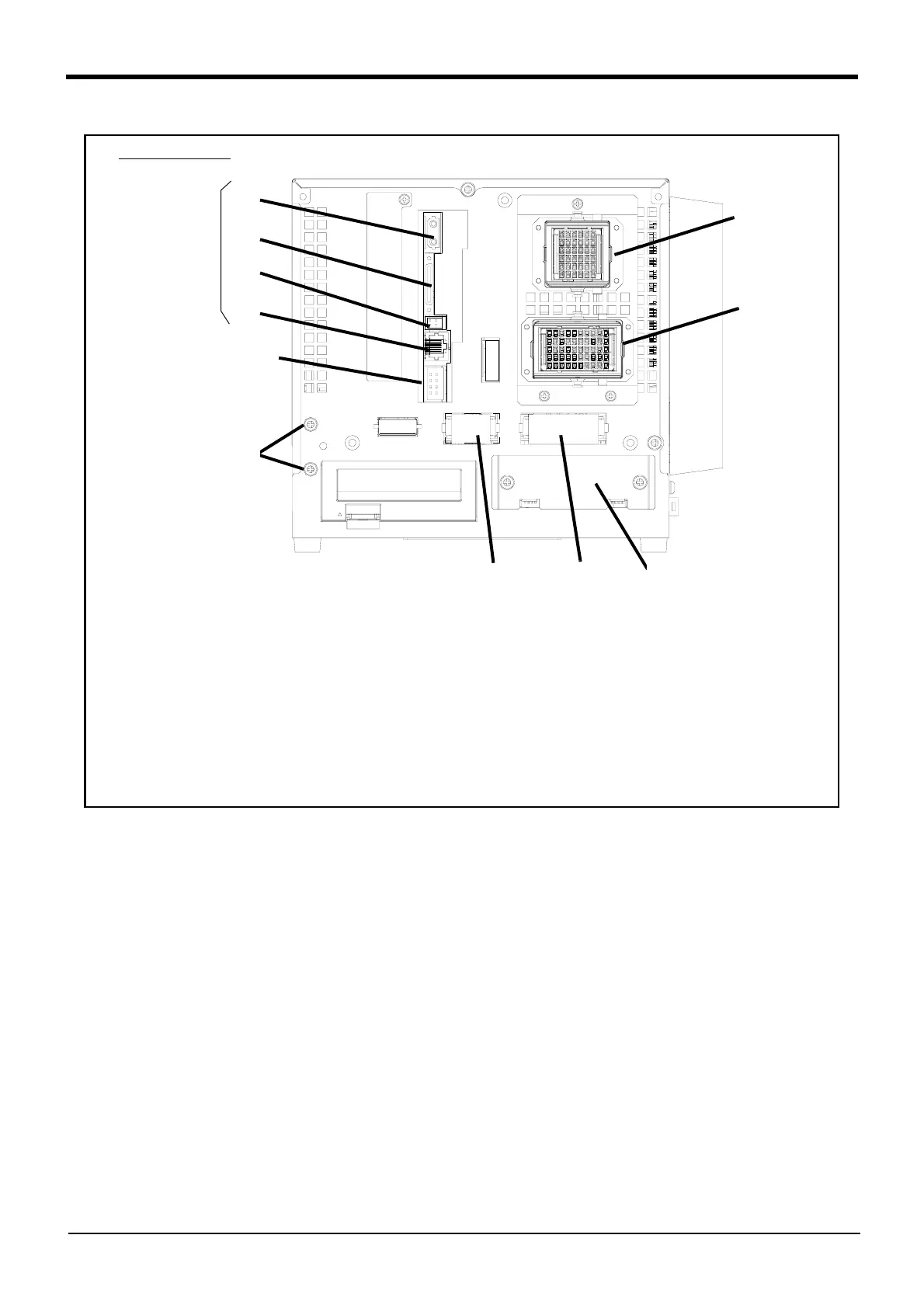
Fig.3-4 : Names of each part (Rear side DU1A-700 series)
DU1A-700 series
①
②
③
④
⑤
⑦
⑥
① Machine cable connector (motor power)(CN1) ...........Connects to the robot arm base. (CN1 connector)
② Machine cable connector (motor signal)(CN2)............Connects to the robot arm base. (CN2 connector)
③ Emergency stop input(EMGIN)...........................................Connect the emergency stop switch to the robot.
④ Emergency stop output(EMGOUT)...................................The robot's error condition is outputted.
⑤ Hand slot(HND)......................................................................... Install the pneumatic hand interface optional.
⑥ Special stop input(SKIP).......................................................Stops the robot immediately.
⑦ OPT1A、 ⑧ CON3、 ⑨ DCOUT、 ⑩ CNDISP ........... Connecting with the robot CPU unit.
⑪ Grounding terminal (2 places).............................................The screw for grounding of the cable
(Peel the sheath of the cable, and fix with cable clamp
attached.)
⑧
⑨
⑩
Connect with
robot CPU unit
⑪
* The figure is Standard specification.
(The CE marking specification is the same.)
 Loading...

