3. WIRING
3-17
3
When using pushbuttons
Using the STOP terminal allows the start signal (forward/reverse rotation) to be self-held. When the
start signal is input once, it is held within the drive unit until the stop signal is input. This function is
not available for other than the start signal.
Sink Logic Source Logic
The terminal SD is a common terminal.
STOP
SD
STF
STR
Drive unit
Reverse
rotation
Stop
Forward
rotation
The terminal PC is a common terminal.
STF
STR
Drive unit
Reverse
rotation
Stop
Forward
rotation
PC
STOP
NOTICE
Do not apply voltages to the contact input terminals.
Do not short the terminals PC and SD. Doing so will damage the unit.
When the terminal PC is used as a power supply terminal, the wiring length should
be within 30m.
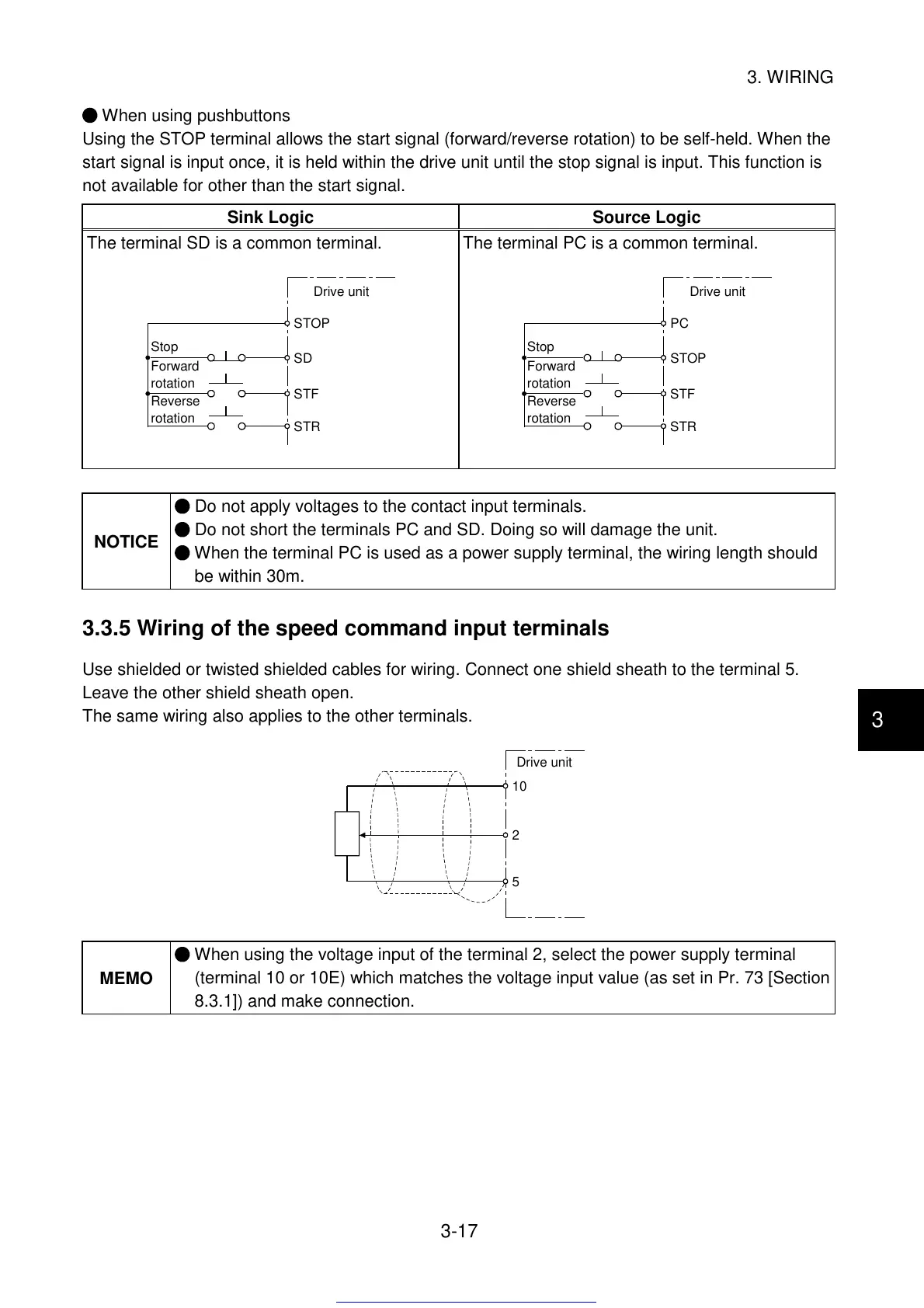
3.3.5 Wiring of the speed command input terminals
Use shielded or twisted shielded cables for wiring. Connect one shield sheath to the terminal 5.
Leave the other shield sheath open.
The same wiring also applies to the other terminals.
10
2
5
Drive unit
MEMO
When using the voltage input of the terminal 2, select the power supply terminal
(terminal 10 or 10E) which matches the voltage input value (as set in Pr. 73 [Section
8.3.1]) and make connection.
Get other manuals https://www.bkmanuals.com
 Loading...


