3. WIRING
3-18
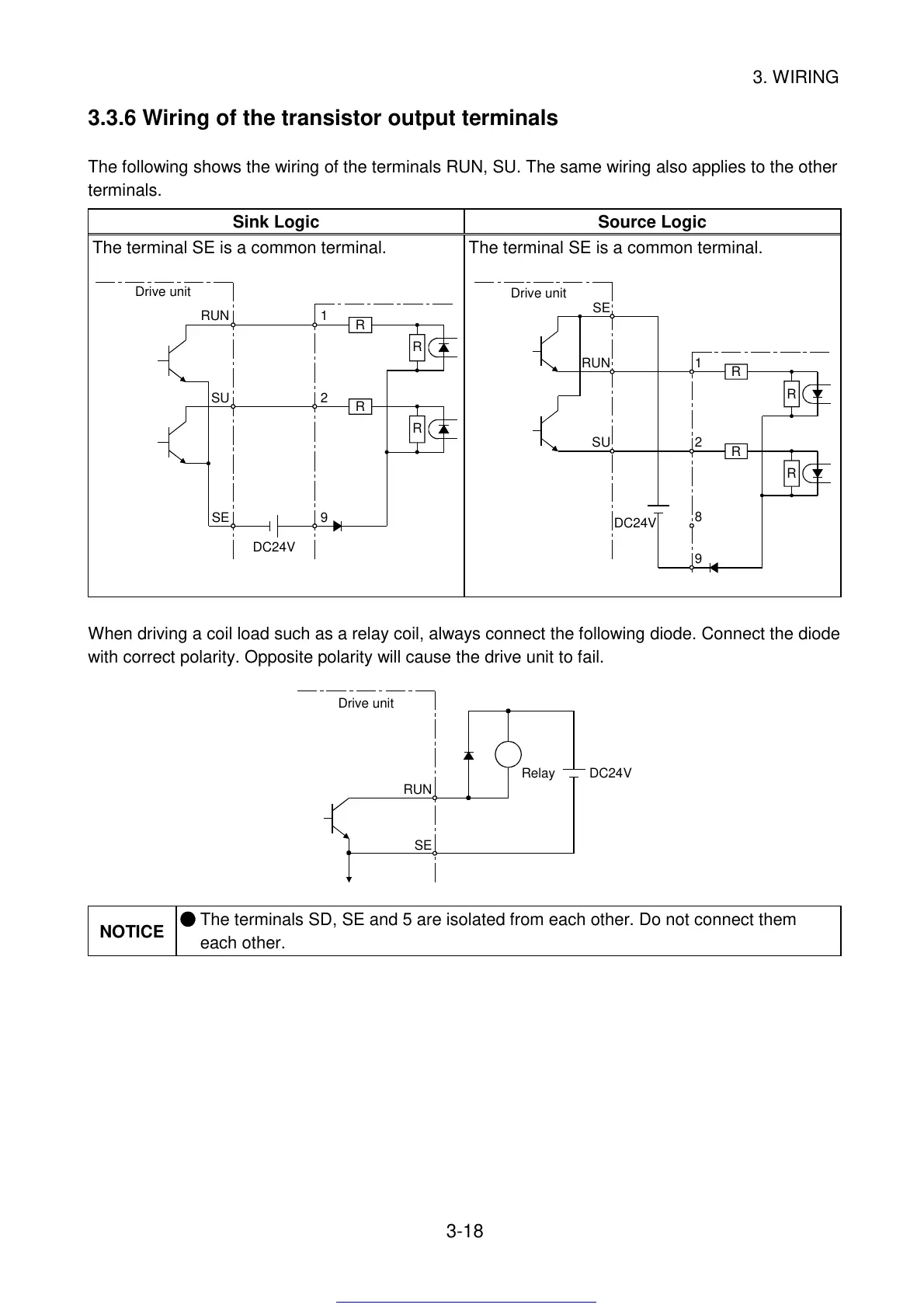
3.3.6 Wiring of the transistor output terminals
The following shows the wiring of the terminals RUN, SU. The same wiring also applies to the other
terminals.
Sink Logic Source Logic
The terminal SE is a common terminal.
RUN
SU
SE
1
2
9
R
R
R
R
DC24V
Drive unit
The terminal SE is a common terminal.
DC24V
RUN
SU
SE
1
2
9
R
R
R
R
8
Drive unit
When driving a coil load such as a relay coil, always connect the following diode. Connect the diode
with correct polarity. Opposite polarity will cause the drive unit to fail.
DC24V
RUN
SE
Relay
Drive unit
NOTICE
The terminals SD, SE and 5 are isolated from each other. Do not connect them
each other.
Get other manuals https://www.bkmanuals.com
 Loading...


