APP - 43
APPENDICES
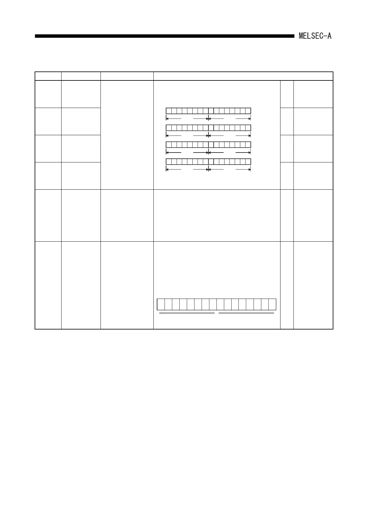
Table App2.2 Special Register List (Continue)
Number Name Description Details
D9180
Limit switch
output state
torage areas for
axes 1 and 2
Bit pattern of limit
switch function output
state
• Stores output state of limit switch function.
—
Dedicated to
A73.
D9181
Limit switch
output state
storage areas
for axes 3 and 4
—
Dedicated to
A73.
D9182
Limit switch
output state
storage areas
for axes 5 and 6
—
Dedicated to
A73.
D9183
Limit switch
output state
storage areas
for axes 7 and 8
—
Dedicated to
A73.
D9184
Cause of PCPU
error
PCPU error code
• Stores error codes occurred at the PCPU in BIN code.
0 : Normal
1 : A73CPU hardware error
2 : PCPU error
10: A70AF error
11: A70AF error
12: A70MDF error
13: AY42 error
—
Dedicated to
A73.
D9185
Servo amplifier
connection data
Bit pattern of servo
amplifier connection
state
• Servo amplifier connection state is checked and the
result is stored in the bit which corresponds to each
axis number.
Connection state is continuously checked. Axes which
changed from disconnected state to connected state
are regarded as connected. But, axes which changed
from connected state to disconnected state are still
regarded as connected.
—
Dedicated to
A73.
b15
Y0F
b14b13 b12 b11 b10 b9 b8 b7 b6 b5 b4 b3 b2 b1 b0
Y0E Y0D Y0C Y0B
Y0A
Y09 Y08 Y07 Y06 Y05 Y04 Y03 Y02 Y01 Y00
Axis 1Axis 2
D9180
Y1F Y1E Y1D Y1C Y1B Y1A Y19 Y18 Y17 Y16 Y15 Y14 Y13 Y12 Y11 Y10
Axis 3Axis 4
D9181
Y2F Y2E Y2D Y2C Y2B Y2A Y29 Y28 Y27 Y26 Y25 Y24 Y23 Y22 Y21 Y20
Axis 5Axis 6
D9182
Y3F Y3E Y3D Y3C Y3B Y3A Y39 Y38 Y37 Y36 Y35 Y34 Y33 Y32 Y31 Y30
Axis 7Axis 8
D9183
"1" is stored in
the bit which
corresponds to
output (Y) which
is turned on. "0"
is stored when
output state is
turned off.
b15 b8
b7
b0
00000000
For
axis
8
For
axis
7
For
axis
6
For
axis
5
For
axis
4
For
axis
3
For
axis
2
For
axis
1
All 0
Connected: 1
Disconnected: 0
to to
 Loading...


