3. SIGNALS AND WIRING
3 - 38
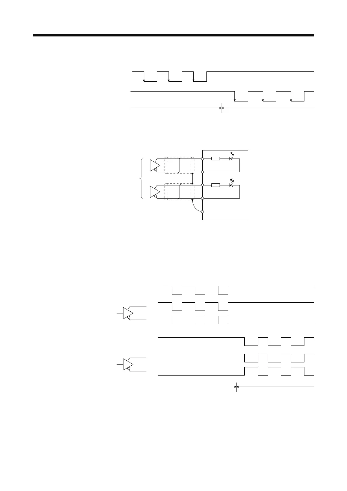
The following section explains about the case where the negative logic and the forward/reverse
rotation pulse trains are set to "_ _ 1 0" in [Pr. PA13].
Reverse rotation commandForward rotation command
(OFF)
(OFF) (OFF)(ON) (ON)
(ON) (OFF) (ON) (OFF) (ON)
(OFF)
Forward rotation pulse train
(transistor)
Reverse rotation pulse train
(transistor)
(ON)
2) Differential line driver type
Connect as follows.
PP
NP
Servo amplifie
PG
NG
SD
Approximately
100Ω
Approximately
100Ω
(Note)
Note. Pulse train input interface is comprised of a photocoupler.
If a resistor is connected to the pulse train signal line, it may malfunction due to
reduction in current.
The following section explains about the case where the negative logic and the forward/reverse
rotation pulse trains are set to "_ _ 1 0" in [Pr. PA13]. The waveforms of PP, PG, NP, and NG are
based on LG.
Reverse rotation
PP
PG
NP
NG
Reverse rotation
pulse train
Forward rotation
pulse train
Forward rotation
 Loading...
