4. STARTUP
4 - 35
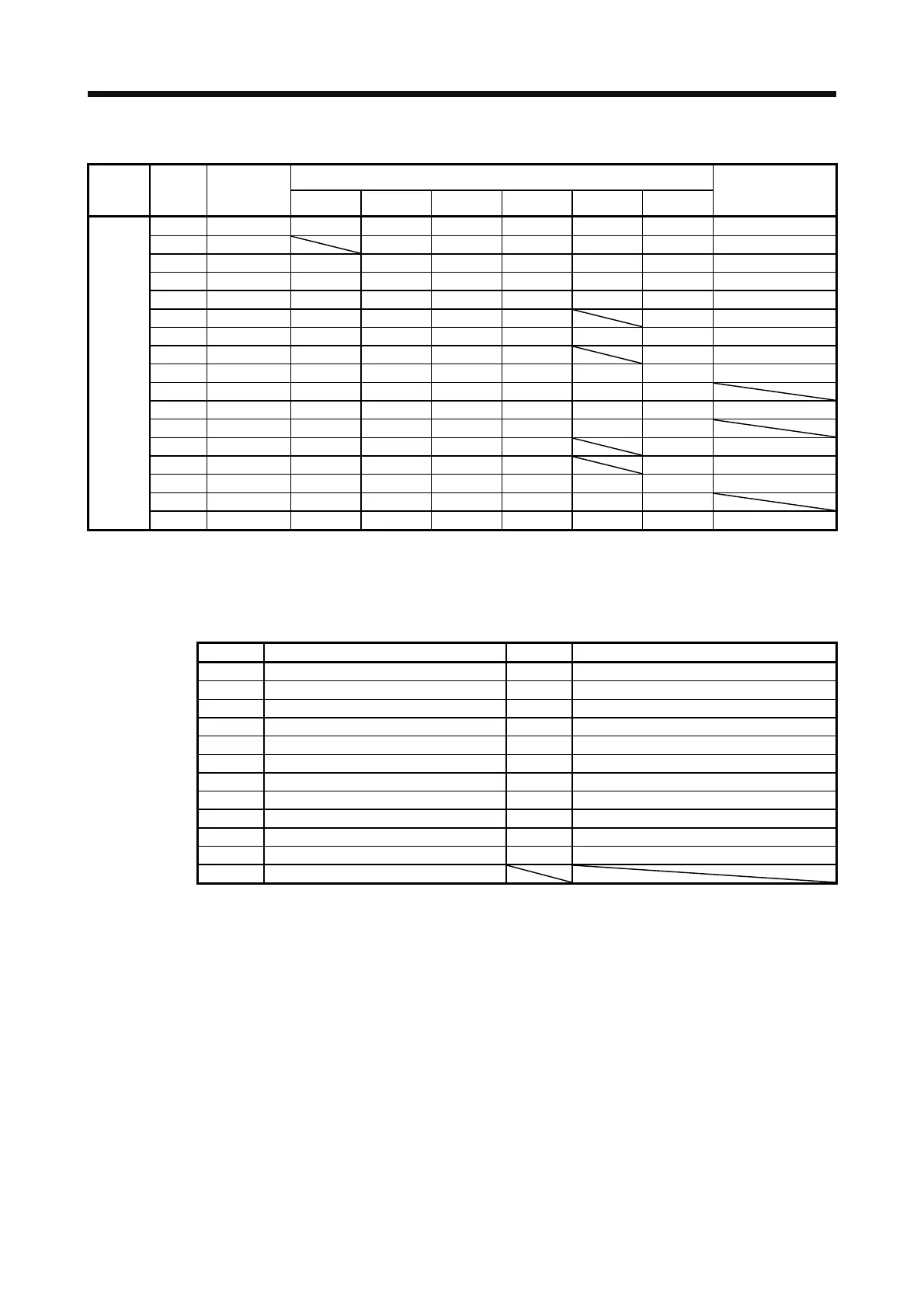
(a) Control modes and I/O signals
(Note 2) Symbols of I/O signals in control modes
Connector Pin No.
Signal
input/output
(Note 1) I/O
P P/S S S/T T T/P
Related parameter
15 I SON SON SON SON SON SON Pr. PD03/Pr. PD04
16 I -/SP2 SP2 SP2/SP2 SP2 SP2/- Pr. PD05/Pr. PD06
17 I PC PC/ST1 ST1 ST1/RS2 RS2 RS2/PC Pr. PD07/Pr. PD08
18 I TL TL/ST2 ST2 ST2/RS1 RS1 RS1/TL Pr. PD09/Pr. PD10
19 I RES RES RES RES RES RES Pr. PD11/Pr. PD12
22 O INP INP/SA SA SA/- -/INP Pr.PD23
23 O ZSP ZSP ZSP ZSP ZSP ZSP Pr. PD24
24 O INP INP/SA SA SA/- -/INP Pr. PD25
CN1 25 O TLC TLC TLC TLC/VLC VLC VLC/TLC Pr. PD26
33 O OP OP OP OP OP OP
41 I CR CR/SP1 SP1 SP1/SP1 SP1 SP1/CR Pr. PD13/Pr. PD14
42 I EM2 EM2 EM2 EM2 EM2 EM2
43 I LSP LSP LSP LSP/- -/LSP Pr. PD17/Pr. PD18
44 I LSN LSN LSN LSN/- -/LSN Pr. PD19/Pr. PD20
45 I LOP LOP LOP LOP LOP LOP Pr. PD21/Pr. PD22
48 O ALM ALM ALM ALM ALM ALM
49 O RD RD RD RD RD RD Pr. PD28
Note 1. I: input signal, O: output signal
2. P: position control mode, S: speed control mode, T: torque control mode
P/S: position/speed control switching mode, S/T: speed/torque control switching mode, T/P: torque/position switching mode
(b) Symbol and signal names
Symbol Application Symbol Application
SON Servo-on RES Reset
LSP Forward rotation stroke end EM2 Forced stop 2
LSN Reverse rotation stroke end LOP Control switching
CR Clear TLC Limiting torque
SP1 Speed selection 1 VLC Limiting speed
SP2 Speed selection 2 RD Ready
PC Proportion control ZSP Zero speed detection
ST1 Forward rotation start INP In-position
ST2 Reverse rotation start SA Speed reached
RS1 Forward rotation selection ALM Malfunction
RS2 Reverse rotation selection OP Encoder Z-phase pulse (open collector)
TL External torque limit selection
 Loading...
