14. COMMUNICATION FUNCTION
14 - 4
14.2 Communication specifications
14.2.1 Outline of communication
Receiving a command, this servo amplifier returns data. The device which gives the command (e.g. personal
computer) is called a master station and the device (servo amplifier) which returns data in response to the
command is called a slave station. When fetching data successively, the master station repeatedly
commands the slave station to send data.
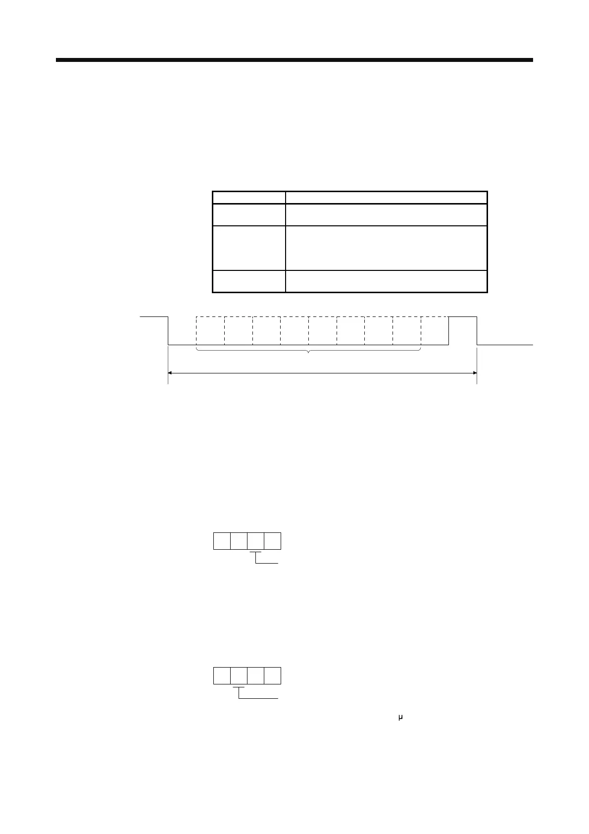
Item Definition
Baud rate [bps]
9600/19200/38400/57600/115200 asynchronous
system
Transfer code
Start bit
Data bit
Parity bit
Stop bit
1 bit
8 bits
1 bit (even)
1 bit
Transfer method
Character method Half-duplex
communication method
1 frame (11 bits)
Data
Start 0 1 2 3 4 5 6 7 Parity Stop
Next
start
(LSB) (MSB)
14.2.2 Parameter setting
When the RS-422 communication function is used to operate the servo, set the communication
specifications of the servo amplifier with the parameters.
To enable the parameter values, cycle the power after setting.
(1) Serial communication baud rate
Select the communication speed. Match this value to the communication speed of the sending end
(master station).
Serial communication baud rate
0: 9600 [bps] 3: 57600 [bps]
1: 19200 [bps] 4: 115200 [bps]
2: 38400 [bps]
[Pr. PC21]
(2) RS-422 communication response delay time
Set the time from when the servo amplifier (slave station) receives communication data to when it
returns data. Set "0" to return data in less than 800 μs or "1" to return data in 800 μs or longer.
RS-422 communication response delay time
0: Disabled
1: Enabled (responding after 800
[Pr. PC21]
s or longer delay time)
(3) Station No. setting
Set the station No. of the servo amplifier to [Pr. PC20]. The setting range is station No. 0 to 31.