J
jchristensenAug 25, 2025
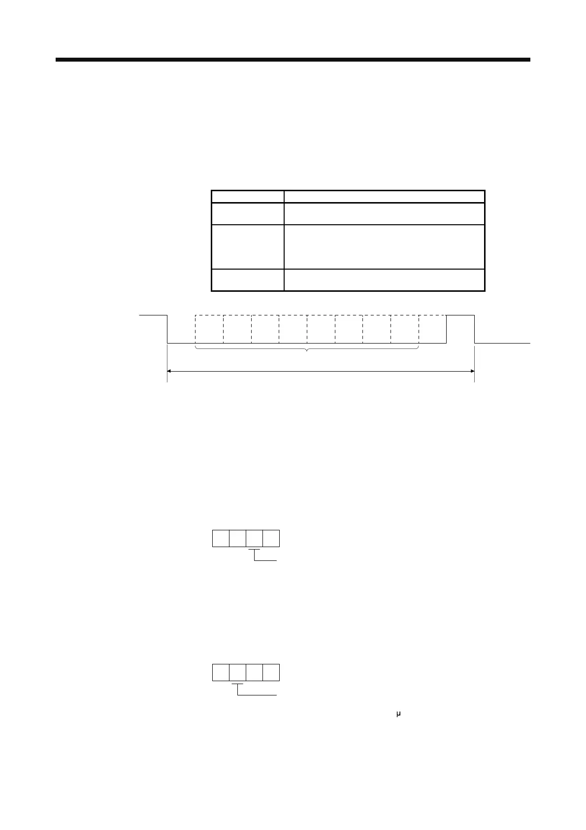
What causes an overspeed error on a Mitsubishi MR-J4-100A?
- DdianedeanAug 25, 2025
An overspeed error on your Mitsubishi Amplifier is caused by abnormal motor speed.
 Loading...
What causes an overspeed error on a Mitsubishi MR-J4-100A?
An overspeed error on your Mitsubishi Amplifier is caused by abnormal motor speed.
| Series | MR-J4 |
|---|---|
| Model | MR-J4-100A |
| Type | Servo Amplifier |
| Voltage Class | 200 V |
| Position Control | Yes |
| Speed Control | Yes |
| Torque Control | Yes |
| Full-closed Control | Yes |
| Advanced One-touch Tuning | Yes |
| Real-time auto-tuning | Yes |
| Vibration Tough Drive | Yes |
| STO (Safe Torque Off) | Yes |
| Weight | 1.5 kg |
| Input Voltage | 200 V |
| Communication Interface | RS-422 |
| Protection Functions | Overcurrent, Overvoltage |
Details the standard specifications for the MR-J4 servo amplifier, including voltage, current, control methods, and protective functions.
Specifies the correct installation direction and required clearances for servo amplifiers to prevent malfunction and ensure proper operation.
Provides instructions and precautions for connecting the input power supply circuit to the servo amplifier and servo motor.
Illustrates connection examples for I/O signals in various control modes, including position, speed, and torque control.
Offers detailed explanations of signals, covering position, speed, and torque control modes, including parameter settings and timing charts.
Explains the forced stop deceleration function (SS1), including connection diagrams, timing charts, and parameter settings for safe operation.
Provides a step-by-step procedure for initial power-on, including wiring checks, parameter settings, and test operations.
Details the startup procedures specific to position control mode, including power on/off, stop methods, and test operations.
Outlines the startup procedures for speed control mode, covering power on/off, stopping the motor, and test operations.
Describes the startup procedures for torque control mode, including power on/off, stopping the motor, and test operations.
Details the basic setting parameters, including operation mode, regenerative option, and absolute position detection system settings.
Lists parameters related to gain and filter settings, such as adaptive tuning, vibration suppression, and notch filters.
Details the basic setting parameters, including operation mode, regenerative option, and absolute position detection system settings.
Lists parameters for gain and filter settings, including adaptive tuning, vibration suppression, and notch filters.
Explains different methods for gain adjustment, including single servo amplifier adjustment and using MR Configurator2.
Describes the one-touch tuning function, executable via MR Configurator2 or push buttons, and lists automatically set parameters.
Explains the auto tuning function, which estimates machine characteristics to set optimum gains, covering Auto tuning modes 1 and 2.
Details the available filters for MR-J4 servo amplifiers, including low-pass filters and machine resonance suppression filters.
Describes the tough drive function, which enables continuous operation even under alarm conditions, preventing vibration and power failure issues.
Provides a comprehensive list of alarms and warnings, including their codes, names, stop methods, and deactivation procedures.
Details the electronic thermal overload protection characteristics of the servo amplifier and servo motor, including graphs for different series.
Explains the dynamic brake operation, including coasting distance calculation and time constants, with graphs for 200 V and 400 V classes.
Details combinations of servo amplifiers with regenerative options and their regenerative power, including selection criteria and connection diagrams.
Provides specifications and system configuration details for MR Configurator2 software used for servo amplifier setup and monitoring.
Details the external dynamic brake, its selection, connection example for 200 V and 400 V classes, and timing charts.
Explains the configuration, specifications, and battery mounting procedure for the MR-BAT6V1SET battery.
Describes the MR-BAT6V1BJ battery for junction battery cable, including its configuration, specifications, and replacement procedures.
Outlines the startup procedure for the absolute position detection system, including battery installation, parameter setting, and home position setting.
Details the absolute position data transfer protocol, including transmission commands, replies, and timing charts for data transfer.
Lists potential absolute position data transfer errors, such as alarms and warnings, and refers to troubleshooting procedures.
Provides essential safety notes for installing, starting-up, repairing, or servicing machines with STO function components.
Lists residual risks associated with the STO function, emphasizing manufacturer responsibility for risk evaluation and Mitsubishi's limited liability.
Details the STO I/O signal connector (CN8) and its signal layouts, including pin configurations and explanations of I/O devices.
Illustrates connection examples for the STO function, including connections to a safety logic unit and external safety relay.
Explains the communication protocol, including transmission data configuration, error codes, checksum, and time-out processing.
Lists and explains error codes used in communication, indicating whether they are for normal or alarm states and their response.
Offers detailed explanations of commands, including data processing for reading and writing, and status display modes.
Describes the test operation mode for checking servo operation, including JOG, positioning, motor-less, and program operations.
Details the startup procedure for linear servo motors, including setting motor types, encoder directions, and performing magnetic pole detection.
Explains the magnetic pole detection process for linear servo motors, detailing methods, parameters, and setting procedures.
Shows the overload protection characteristics of the servo amplifier for linear servo motors, with graphs illustrating operation time vs. load ratio.
Details the startup procedure for direct drive servo systems, including installation, magnetic pole detection, and controller checks.
Explains the magnetic pole detection process for direct drive motors, covering methods, parameters, and setting procedures.
Describes the absolute position detection system for direct drive motors, including operating conditions, alarms, and data transfer.
Provides a startup procedure for fully closed loop systems, covering installation, configuration, and operation checks.
Details the absolute position detection system for fully closed loop systems using linear encoders, including conditions and restrictions.
Details the MR-J3-D05 Safety Logic Unit, including package contents, safety terms, and emergency operation procedures.
Provides troubleshooting steps for issues such as no power supply or FAULT LED indication, and suggests appropriate actions.

