APPENDIX
App. - 4
App. 4.2.1 Professional engineer
Only professional engineers should mount MR-J4 servo amplifiers.
Here, professional engineers should meet the all conditions below.
(1) Persons who took a proper engineering training or qualified persons who are engaged in electrical
equipment
Please note if you can take proper engineering training at your local Mitsubishi Electric office. Contact
your local sales office for schedules and locations.
(2) Persons who can access to operating manuals for the protective devices (e.g. light curtain) connected to
the safety control system. A person who have read and familiarized himself/herself with the manuals.
App. 4.2.2 Applications of the devices
MR-J4 servo amplifiers comply with the following safety standards.
ISO/EN ISO 13849-1 Category 3 PL d, IEC/EN 62061 SIL CL 2, IEC/EN 61800-5-2 SIL 2 (STO), IEC/EN
61800-5-1, IEC/EN 61800-3, IEC/EN 60204-1
In addition, MR-J4 servo amplifiers can be used with the MR-J3-D05 safety logic unit or safety PLC.
App. 4.2.3 Correct use
Always use the MR-J4 servo amplifiers within specifications (voltage, temperature, etc. Refer to each
instruction manual for details.). Mitsubishi Electric Co. accepts no claims for liability if the equipment is used
in any other way or if modifications are made to the device, even in the context of mounting and installation.
WARNING
It takes 15 minutes for capacitor discharging. Do not touch the unit and terminals
immediately after power off.
(1) Peripheral device and power wiring
The followings are selected based on IEC/EN 61800-5-1, UL 508C, and CSA C22.2 No.14.
(a) Local wiring and crimping tool
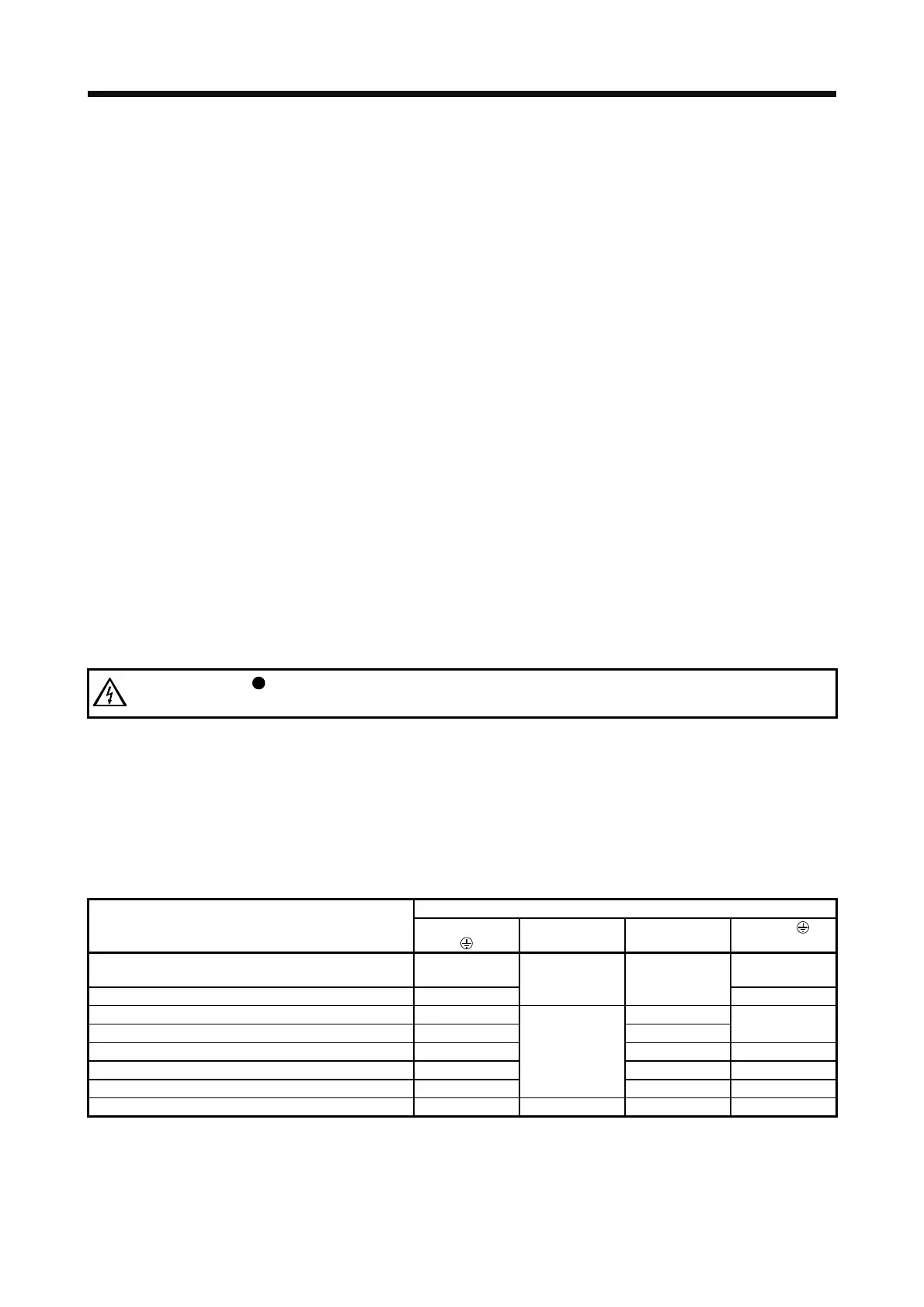
Use only copper wires rated at 75 ˚C for wiring. The following table shows the wire sizes [AWG] and
the crimp terminal symbols rated at 75 ˚C.
1) 200 V class
Wire [AWG] (Note 2)
Servo amplifier
L1/L2/L3
L11/L21 P+/C
U/V/W/
(Note 3)
MR-J4-10_/MR-J4-20_/MR-J4-40_/MR-J4-60_/
MR-J4-70_/MR-J4-100_/MR-J4-200_
14 14
MR-J4-350_ 12
14 14
12
MR-J4-500_ (Note 1) 10: a 14: c
MR-J4-700_ (Note 1) 8: b 12: a
8: b
MR-J4-11K_ (Note 1) 6: d 12: e 4: f
MR-J4-15K_ (Note 1) 4: f 10: e 2: g
MR-J4-22K_ (Note 1) 1/0: h
14: c
10: i 2/0: j
MR-J4W_-_B 14 (Note 4) 14 14 14
Note 1. To connect these models to a terminal block, be sure to use the screws that come with the terminal block.
2. Alphabets in the table indicate crimping tools. Refer to the following table for the crimp terminals and crimping tools.
3. Select wire sizes depending on the rated output of the servo motors. The values in the table are sizes based on rated output of
the servo amplifiers.
4. Use the crimp terminal c for the PE terminal of the servo amplifier.
 Loading...
