3. SIGNALS AND WIRING
3 - 30
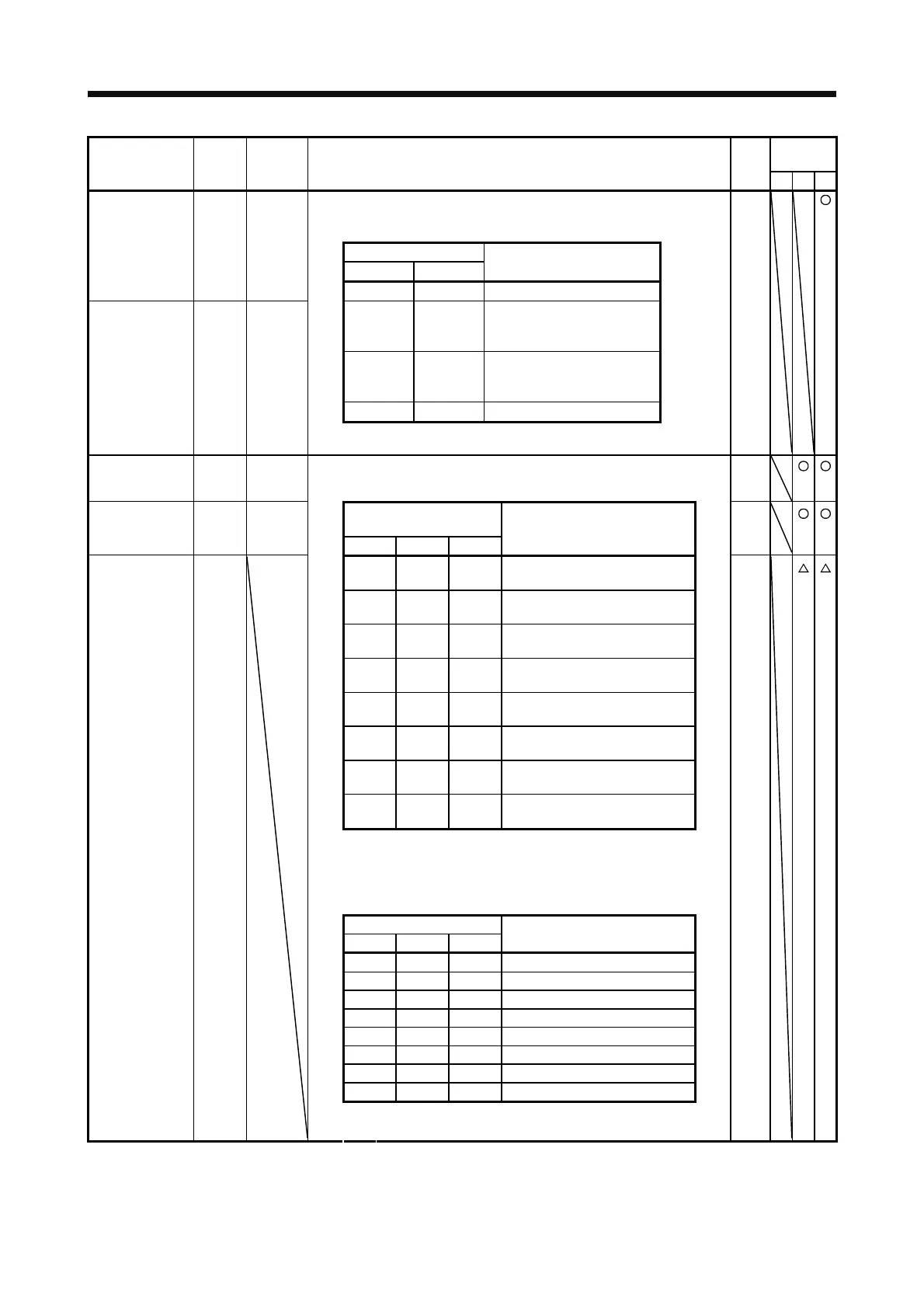
Control
mode
Device Symbol
Connector
pin No.
Function and application
I/O
division
PST
Forward rotation
selection
RS1 CN1-18 This is used to select a servo motor torque generation directions.
The following shows the torque generation directions.
DI-1
(Note) Input device
RS2 RS1
Torque generation direction
0 0 Torque is not generated.
Reverse rotation
selection
RS2 CN1-17
0 1
Forward rotation in power
running mode/reverse rotation
in regenerative mode
1 0
Reverse rotation in power
running mode/forward rotation
in regenerative mode
1 1 Torque is not generated.
Note. 0: Off
1: On
Speed selection
1
SP1 CN1-41 1. For speed control mode
This is used to select the command speed for operation.
DI-1
Speed selection
2
SP2 CN1-16
(Note) Input device
DI-1
SP3 SP2 SP1
Speed command
Speed selection
3
SP3
0 0 0 VC (Analog speed command)
DI-1
0 0 1
Pr. PC05 Internal speed
command 1
0 1 0
Pr. PC06 Internal speed
command 2
0 1 1
Pr. PC07 Internal speed
command 3
1 0 0
Pr. PC08 Internal speed
command 4
1 0 1
Pr. PC09 Internal speed
command 5
1 1 0
Pr. PC10 Internal speed
command 6
1 1 1
Pr. PC11 Internal speed
command 7
Note. 0: Off
1: On
2. For the torque control mode
This is used to select the limit speed for operation.
(Note) Input device
SP3 SP2 SP1
Speed limit
0 0 0 VLA (Analog speed limit)
0 0 1 Pr. PC05 Internal speed limit 1
0 1 0 Pr. PC06 Internal speed limit 2
0 1 1 Pr. PC07 Internal speed limit 3
1 0 0 Pr. PC08 Internal speed limit 4
1 0 1 Pr. PC09 Internal speed limit 5
1 1 0 Pr. PC10 Internal speed limit 6
1 1 1 Pr. PC11 Internal speed limit 7
Note. 0: Off
1: On
 Loading...
