BALANCER CHAIN <4B12>
ENGINE OVERHAUL
11B-49
INSTALLATION SERVICE POINTS
>>A<< LADDER FRAME INSTALLATION
CAUTION
Be sure to remove liquid gasket that has entered
mounting holes.
1. Completely remove liquid gasket adhering to the
cylinder block and ladder frame.
CAUTION
Sufficiently check that there is no residual oil on
the place where degreasing is performed. If fin
-
gerprints are left, do not touch it with bare hands
after the degreasing, since the oils from your fin
-
gers will harm the seal ability.
2. Degrease the surface where the liquid gasket is
applied and the contact surface between the
cylinder block and ladder frame.
AK502868
1 mm
8.5 mm
3 mm
8.5 mm
1.75 mm
3 mm
AC
3. Squeeze liquid gasket of φ2.5 ± 0.5 mm in
thickness and apply it to the illustrated position of
the ladder frame.
Specified sealant:
ThreeBond 1217G or equivalent
AKB00722
AB
1
3
6
2
4
5
7
9
8
10
4. Tighten the ladder frame to the specified torque of
24
± 2 N⋅m in the order shown in the illustration.
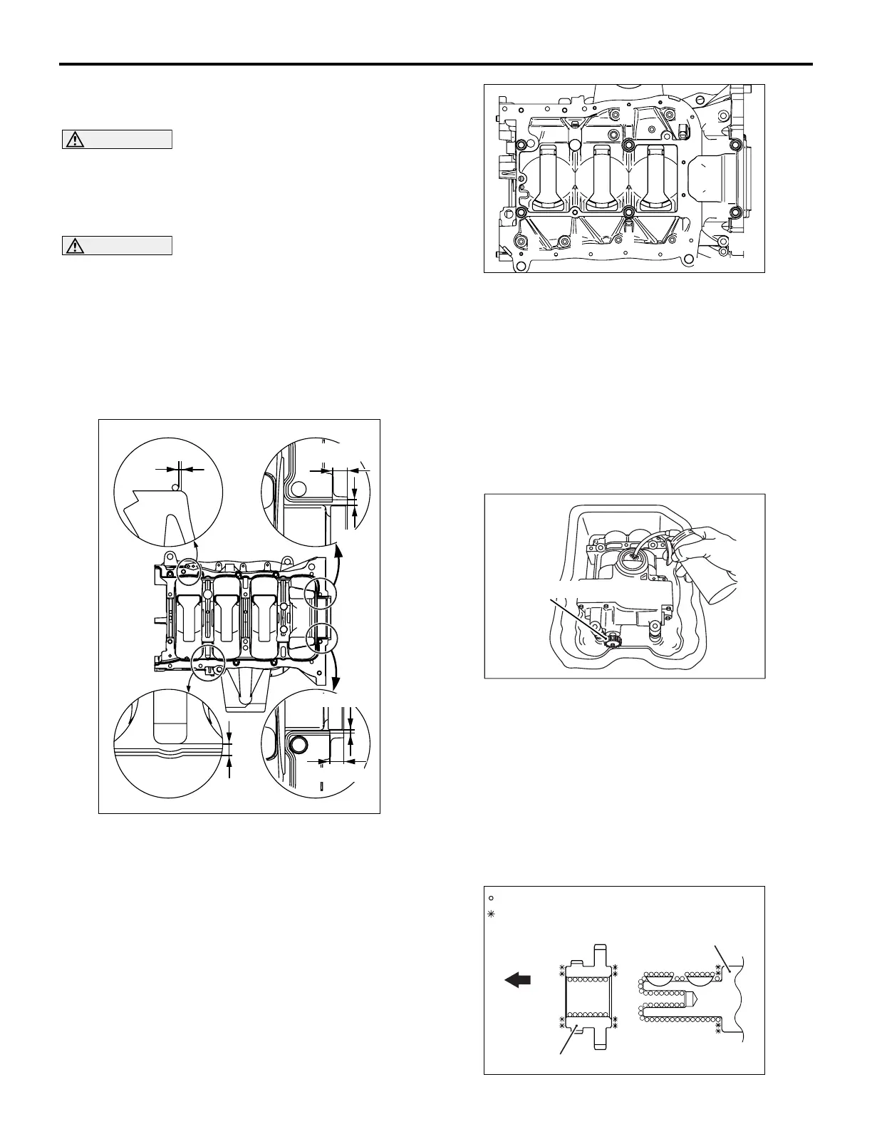
>>B<< CRANKSHAFT SPROCKET /
BALANCER CHAIN / BALANCER SHAFT
MODULE INSTALLATION
When the new balancer shaft module is installed,
supply oil to the oil pump and the balancer shaft
bearing in the balancer shaft module using the fol
-
lowing procedures.
AK503559
AC
Balancer shaft sprocket
a. Clean the inside of the removed oil pan. Put the
balancer shaft module carefully into the oil pan so
that the oil inlet can be upward.
b. Pour the engine oil so that the two-third of the
balancer module can be immersed.
c. Also, pour approximate 50 cc of engine oil from
the oil inlet.
d. By giving four clockwise rotations or more to the
balancer shaft sprocket, the oil is supplied to the
oil pump and the balancer shaft bearing.
AK603521
AE
Crankshaft sprocket
Crankshaft
Engine
front
: Wipe clean with a rag.
: Wipe clean with a rag and degrease.

 Loading...