AK305607
AF
Identification
number
2
PISTON AND CONNECTING ROD
ENGINE OVERHAUL
11B-57
3. A connecting rod bearing has an identification
mark at the illustrated position.
>>F<< CONNECTING ROD CAP
INSTALLATION
NOTE: The connecting rod resulting from the break-
ing process has the high insertion force. The new
connecting rod assembly may possibly be difficult to
remove the connecting rod.
If difficult to remove it, alternately strike the two bolt
heads with a plastic hammer while the connecting
rod bolt is slightly loosened, or strike the centre of the
cap shaft’s inside diameter slightly and outward.
If the outside of the cap is directly struck, the lateral
force is added to the broken-out section. Thus, pay
attention to the broken-out section that might be diffi
-
cult to be separated or might fall.
Clean the broken-out section before the installation
to the engine, using compression air.
AK503157
2
Cylinder No.
AD
Notch
Front mark
1. Assemble the bearing cap on the connecting rod
by aligning it with the mark put during removal. If a
new connecting rod without a mating mark is
used, assemble so that the detent notch of the
bearing is on the same side as illustrated.
AK502752
2. Make sure that clearance of the thrust of the
connecting rod big end is appropriate.
Standard value: 0.10 − 0.25 mm
Limit: 0.4 mm
>>G<< CONNECTING ROD CAP BOLT
INSTALLATION
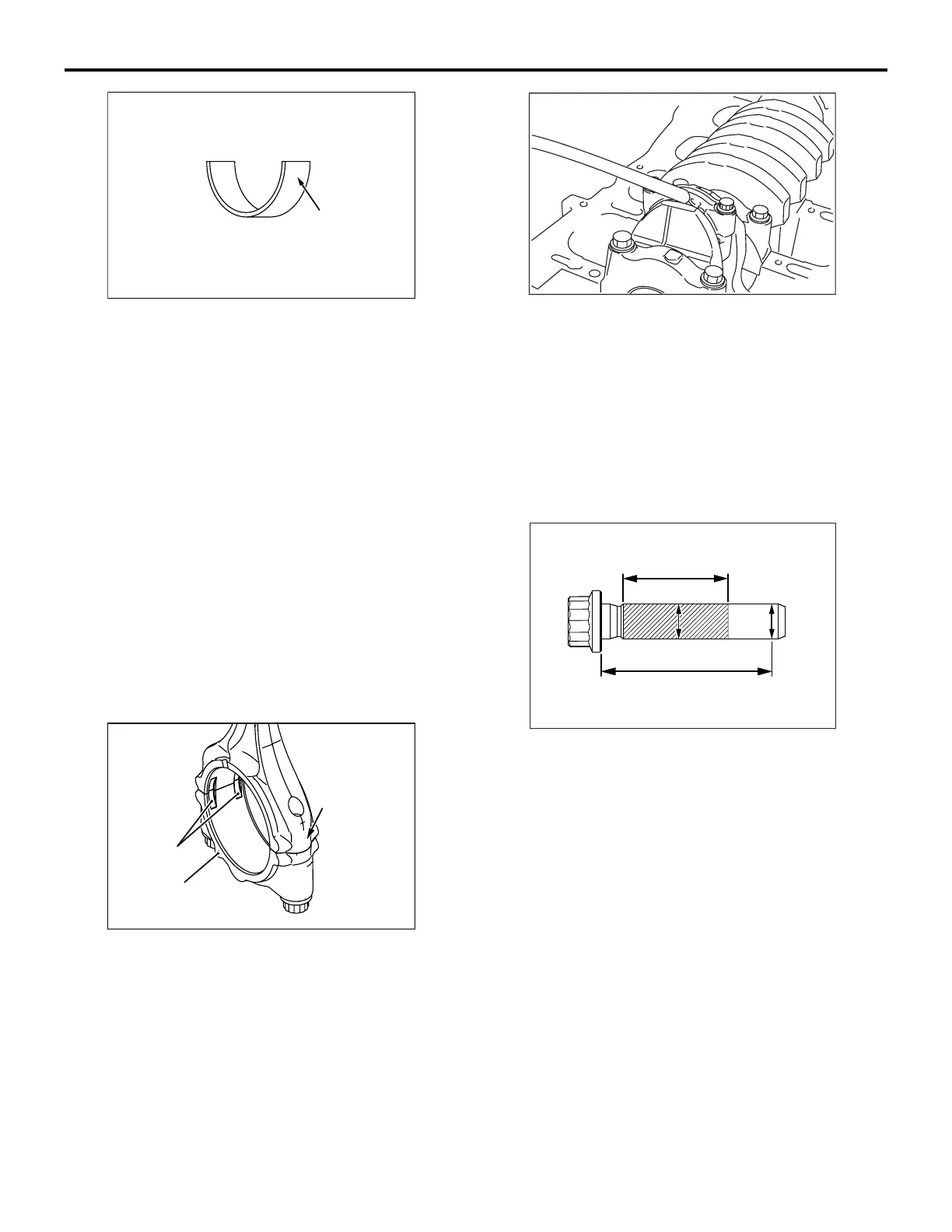
1. Check in the following procedure before reusing
the connecting rod bolt.
AK604589
AE
20.5 mm
35 mm
A
BB
X
(1) Measure the outside diameter "A."
(2) Measure the smallest outside diameter "B"
within the range "X" shown in the illustration.
(3) If the difference of outside diameter of thread
exceeds the limit, replace the connecting rod
bolt.
Limit: 0.1 mm
2. Apply engine oil to the threaded portion and seat
surface of the bolt before installing it.
3. After installing each bolt and tightening it by
fingers, tighten bolts alternately to properly
assemble the cap.
4. Tighten the bolt in several steps until the torque
reaches 5.0 N
⋅m.
5. Tighten the bolt in several steps until the torque
reaches 20 N
⋅m.

 Loading...