Chapter 11 Body
15.4 Remove the interior door handle screws (arrows) from
the body
15.7 Remove the four screws holding the latch assembly to
the door
15.8 The exterior handle is attached to the door with two bolts
that are accessible from the inside
4 Remove the screws that retain the interior handle assembly and lift it
out (see illustration).
5 Remove the glass run channel.
6 Disengage the door lock rod from the door latch assembly.
7 Remove the door latch assembly mounting screws (see illustration)
and lift out the door latch assembly.
8 If necessary, remove the two nuts retaining the exterior handle and lift
it out (see illustration).
9 Remove the door lock cylinder through the outside of the door (see
illustrations).
IO Installation is the reverse of removal. Note: DW~ginsfa//ation, apply
grease to the sliding surface of a// levers and springs.
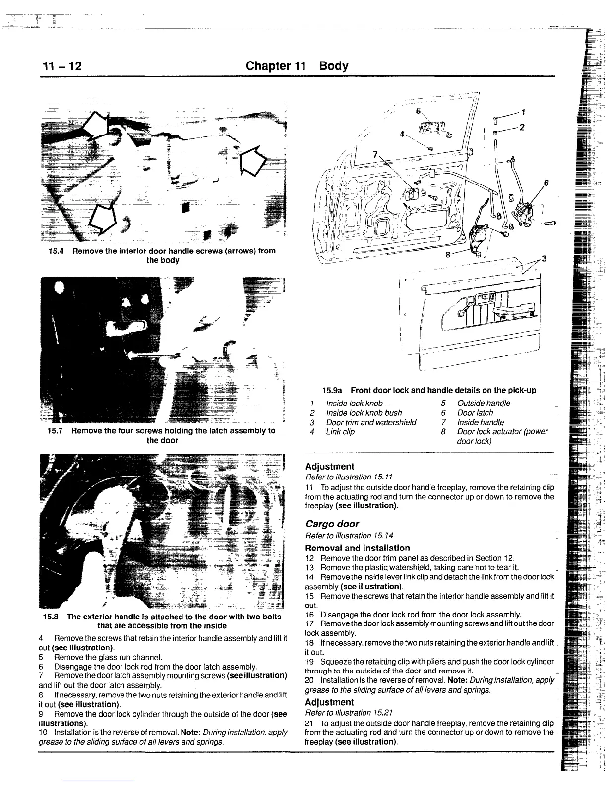
15.9a Front door lock and handle details on the pick-up
1 inside lock knob 5 Outside handle
2 Inside lock knob bush 6 Door latch
3 Door trim znd watershield 7 Inside handle
4 Link clip
8 Door lock actuator (power
door lock)
Adjustment
Refer to illustration 15. f 7
11 To adjust the outside door handle freeplay, remove the retaining clip
from the actuating rod and turn the connector up or down to remove the
freeplay (see illustration).
Cargo door
Refer to illustration 15.14
Removal and installation
12 Remove the door trim panel as described in Section 12.
13 Remove the plastic watershield, taking care not to tear it.
14 Removetheinsideleverlinkclipanddetachthelinkfromthedoorlock
assembly (see illustration).
15 Remove the screw-s that retain the interior handle assembly and Ii&it
out.
16 Disengage the door lock rod from the door lock assembly.
17 Remove the door lock assembly mounting screws and lift out the door
lock assembly.
18 If necessary, remove the two nuts retaining the exterior-handle and lift
it out.
19 Squeeze the retaining clip with pliers and push the door lock cylinder
through to the outside of the door and remove it.
20 Installation is the reverse of removal. Note: During installation, apply-
grease to the sliding surface of all levers and springs.
Adjustment
Refer to illustration 15.21
21 To adjust the outside door handle freeplay, remove the retaining clip
from the actuating rod and turn the connector up or down to remove the_
freeplay (see illustration).
 Loading...


