I I
: i
9-6
Chapter 9 Brakes
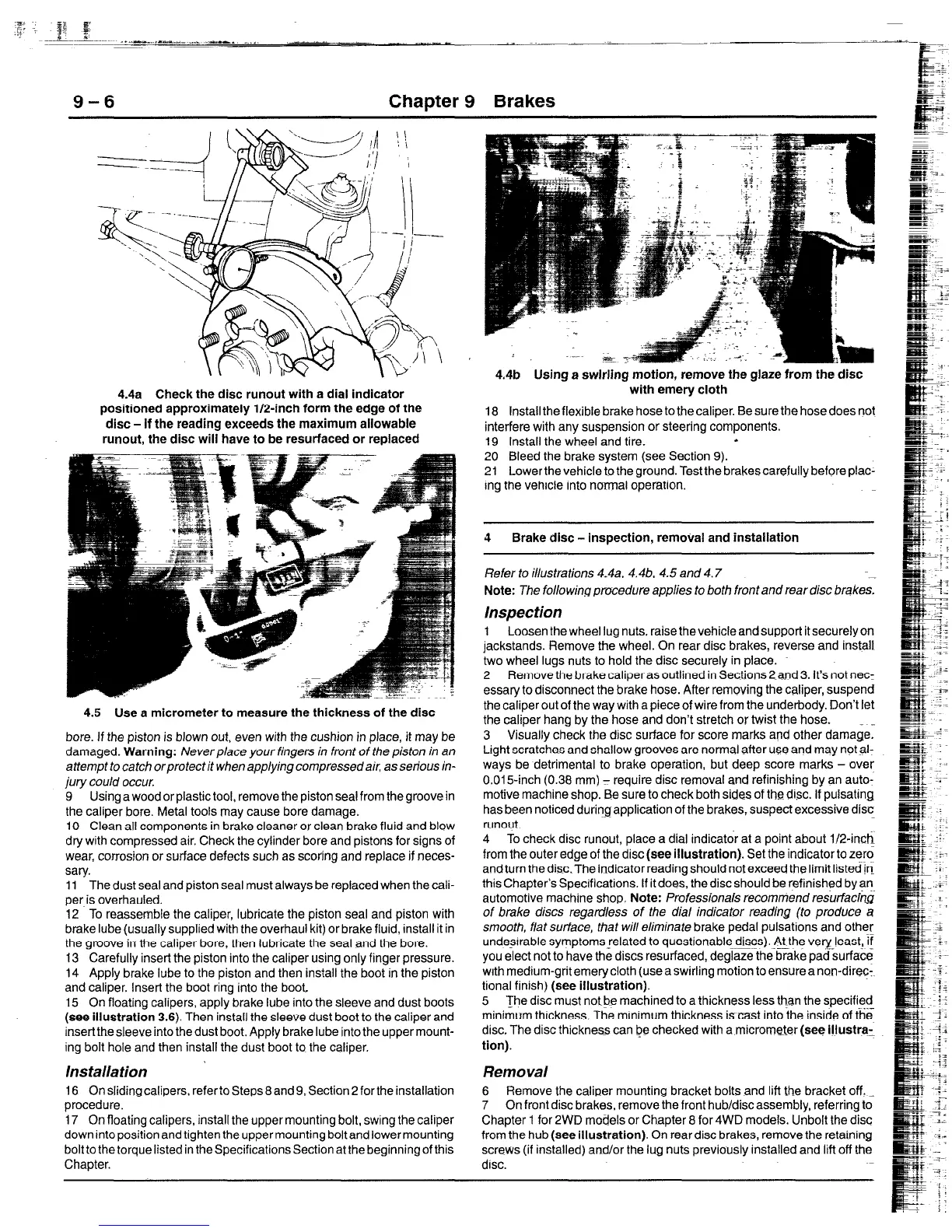
4.4a Check the disc runout with a dial indicator
positioned approximately l/2-inch form the edge of the
disc - if the reading exceeds the maximum allowable
runout, the disc will have to be resurfaced or replaced
4.5 Use a micrometer to measure the thickness of the disc
bore. If the piston is blown out, even with the cushion in place, it may be
damaged. Warning: Neverplace your fingers in front of the piston in an
attempt to catch orprotect it when applying compressed air, as serious in-
jury could occur.
9 Using a wood or plastic tool, remove the piston seal from the groove in
the caliper bore. Metal tools may cause bore damage.
10 Clean all components in brake cleaner or clean brake fluid and blow
dry with compressed air. Check the cylinder bore and pistons for signs of
wear, corrosion or surface defects such as scoring and replace if neces-
sary.
11 The dust seal and piston seal must always be replaced when the cali-
per is overhauled.
12 To reassemble the caliper, lubricate the piston seal and piston with
brake lube (usually supplied with the overhaul kit) or brake fluid, install it in
the groove in the caliper bore, then lubricate the seal and the bore.
13 Carefully insert the piston into the caliper using only finger pressure.
14 Apply brake lube to the piston and then install the boot in the piston
and caliper. Insert the boot ring into the boot
15 On floating calipers, apply brake lube into the sleeve and dust boots
(see illustration 3.6). Then install the sleeve dust boot to the caliper and
insertthe sleeve into the dust boot. Apply brake lube into the upper mount-
ing bolt hole and then install the dust boot to the caliper.
’ Ins talla tion
16 On sliding calipers, refer to Steps 8 and 9, Section 2 for the installation
procedure.
17 On floating calipers, install the upper mounting bolt, swing the caliper
down into position and tighten the upper mounting bolt and lower mounting
bolt to the torque listed in the Specifications Section at the beginning of this
Chapter.
4.4b Using a swirling motion, remove the glaze from the disc
with emery cloth
18 Install the flexible brake hose to the caliper. Be sure the hose does not
interfere with any suspension or steering components.
19 Install the wheel and tire.
s
20 Bleed the brake system (see Section 9).
21 Lower the vehicle to the ground. Test the brakes carefully before piac-
ing the vehicle into normal operation.
4 Brake disc - inspection, removal and installation
Refer to illustrations 4-4a. 4.4b. 4.5 and 4.7
-
Note: The following procedure applies to both front and rear disc brakes.
Inspection
1 Loosen the wheel Itug nuts, raise the vehicle and support it securelyon
jackstands. Remove the wheel. On rear disc brakes, reverse and install
two wheel lugs nuts to hold the disc securely in place.
2 Remove the brake caliper as outlined in Sections 2~and 3. It’s not net:
essary to disconnect the brake hose. After removing the caliper, suspend
the caliper out of the way with a piece of wire from the underbody. Don’t let
the caliper hang by the hose and don’t stretch or twist the hose. . _
3 Visually check the disc surface for score marks and other damage.
Light scratches and shallow grooves are normal after use and may notal-
ways be detrimental to brake operation, but deep score marks - over
0.015-inch (0.38 mm) - require disc removal and refinishing by an auto-
motive machine shop. Be sure to check both sides of
the
disc. If pulsating
has been noticed during application of the brakes, suspect excessive disc
runout.
4 To check disc runout, place a dial indicator at a point about 1/24nch
from the outer edge of the disc (see illustration). Set the indicator to zero
and turn the d&The indicatorreading should not exceed the limit listed !n
this Chapter’s Specifications. If it does, the disc should be refinished by an
automotive machine shop Note: Professionals recommend res&faci~
of brake discs regardless of the dial indicator reading (to produce a
smooth. f/at surface, that will eliminate brake pedal pulsations and other
undesrrable symptomsrelated to questionable discs). At the very least, If
-
you elect not to have the discs resurfaced, deglaze the brake pad surface
wrth medium-grit emery cloth (use a swirling motion to ensure a non-dire?:.
tional finish) (see illustration).
5 The disc must notbe machined to a thickness less than the specified
_..-
minimum thickness. The mrnimum thickness is cast into the inside of the
disc. The disc thickness can be checked with a micrometer (see illustra:
tion).
Removal
6 Remove the caliper mounting bracket bolts and lift the bracket off. =
7 On front disc brakes, remove the front hub/discassembly, referring to
Chapter 1 for 2WD models or Chapter 8 for 4WD models. Unbolt the disc
from the hub (see illustration). On rear disc brakes, remove the retaining
screws (if installed) and/or the lug nuts previously installed and lift off the
disc.
 Loading...


