Chapter 9 Brakes
4.7 Remove the bolts from the disc/hub assembly, then
separate the two components (it may be necessary to
tap the disc off with a hammer and a block of wood)
Ins talla tion
8 On front disc brakes, install the disc to the hub, tightening the bolts to
the torque listed in this Chapter’s Specifications in a criss-cross pattern.
9 On front disc brakes, install the front disc and hub assembly and ad-
just the wheel bearing (see Chapter 1 [2WD] or Chapter 8 [4WD]).
10 On rear-disc brakes, slide the disc back into place. It’s not necessary
to reinstall the retaining screw.
11 Install the caliper mounting bracket, tightening the mounting bolts to
the torques listed in this Chapter’s Specifications. Position the pads in the
bracket and install the caliper (refer to Section 3 forthe caliper installation
procedure, if necessary). Tighten the caliper bolts to the torque listed in
this Chapter’s Specifications.
12 Install the wheel, then lower the vehicle to the ground. Depress the
brake pedal a few times to bring the brake pads into contact with the disc.
Bleeding of the system will not be necessary unless the brake hose was
disconnected from the caliper. Check the operation of the brakescarefully
before placing the vehicle into normal service.
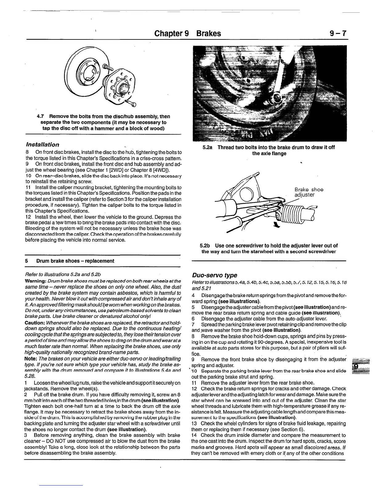
5.2a Thread two bolts into the brake drum to draw it off
the axle flange
*
5
Drum brake shoes -replacement
5.2b Use one screwdriver to hold the adjuster lever out of
the way and turn the starwheel with a second screwdriver
Refer to illustrations 5.2a and 5.2b
Warning: Drum brake shoes must be replacedon both rear wheels at the
same time -never replace the shoes on only one wheel. Also, the dust
created by the brake system may contain asbestos, which is harmful to
yourhealth. Neverblowitout with compressedairanddon’tinhale any of
it. Anapprovedfitteringmaskshouldbe worn when working on the brakes.
Do not, underany circumstances, use petroleum-basedsolvents to clean
brake parts. Use brake cleaner or denatured alcohol only!
Caution: Wheneverthe brakeshoesarereplaced, theretractorandhold-
down springs should also be replaced. Due to the continuous heating/
cooling cycle that the .sQrings are subjected to, they lose their tension over
aperfodoftimeandmayallow theshoes todragon thedrumandwearata
much faster rate than normal. When replacing the brake shoes, use only
high-quality nationally recognized brand-name parts.
Note: The brakes on your vehicle are either duo-servo or leading/trailing
type. If you’re not sure which type your vehicle has, study the brake as-
sembly with the drum removed and compare it to illustrations 5.4a and
5.28.
1 Loosen the wheel lug nuts, raise thevehicleand support it securely on
jackstands. Remove the wheel(s).
2 Pull off the brake drum. if you have difficulty removing it, screw an 8
mm bolt into each of the two threaded holesin the drum (see illustration).
Tighten each bolt one-half turn at a time to back the drum off the axle
flange. It may be necessary to retract the brake shoes away from the in-
side of the drum. This is accomplished by removing the rubber plug in the
backing plate and turning the adjuster star wheel with a screwdriver until
the shoes no longer contact the drum (see illustration).
3 Before removing anything, clean the brake assembly with brake
cleaner - DO NOT use compressed air to blow the dust from the brake
assembly! Take a long, close look at the relationship between the parts
before disassembling the brake assembly.
Duo-servo type
Refertoillustrations5.4a,5.46,5.4~, 5.5a,5.5b,5.7,5.12,5.15,5.16,5.18
and 5.21
4 Disengagethe brake return springs from thepivotand remove thefor-
ward spring (see illustrations).
5 Disengage the adjustercable from the pivot (see illustration) and re-
move the rear brake return spring and cable guide (see illustration);
6 Disengage the adjuster cable from the auto-adjuster lever.
7 Spread the parking brake leverprvot retaining clip and remove the clip
and.wave washer from the pivot (see illustration).
8 Remove the brake shoe hold-down cups, springs and pins by press-
ing in on the cup and rotating it go-degrees. A special, inexpensive tool is
available at auto parts stores for this purpose, but a pair of pliers will suf-
fice.
9 Remove the front brake shoe by disengaging it from the adjuster
spring and adjuster.
‘IO Separate the parking brake lever from the rear brake shoe and slide
out the parking brake strut and spring.
11 Remove the adjuster lever from the rear brake shoe.
12 Check the brake return springs for cracks and other damage. Check
adjuster lever and the adjusting latch forwearand damage. Make sure the
star wheel can be s.crewed into and out of the adjuster. Clean the star
wheel threads and lubricate them with high-temperature grease if any re-
sistance is felt. Measure the adjusting cable length and compare this mea-
surement to the specifications (see illustration).
13 Check the wheel cylinders for signs of brake fluid leakage, repairing
them or replacing them if necessary (see Section 6).
14 Check the drum inside diameter and compare the measurement to
the one cast into the drum. Inspect the drum for hard spots, cracks, score
marks and grooves. Hard spots will appear as small discolored areas. If
they can’t be removed with emery cloth or if any of the other conditions
 Loading...


