Chapter 9 Brakes
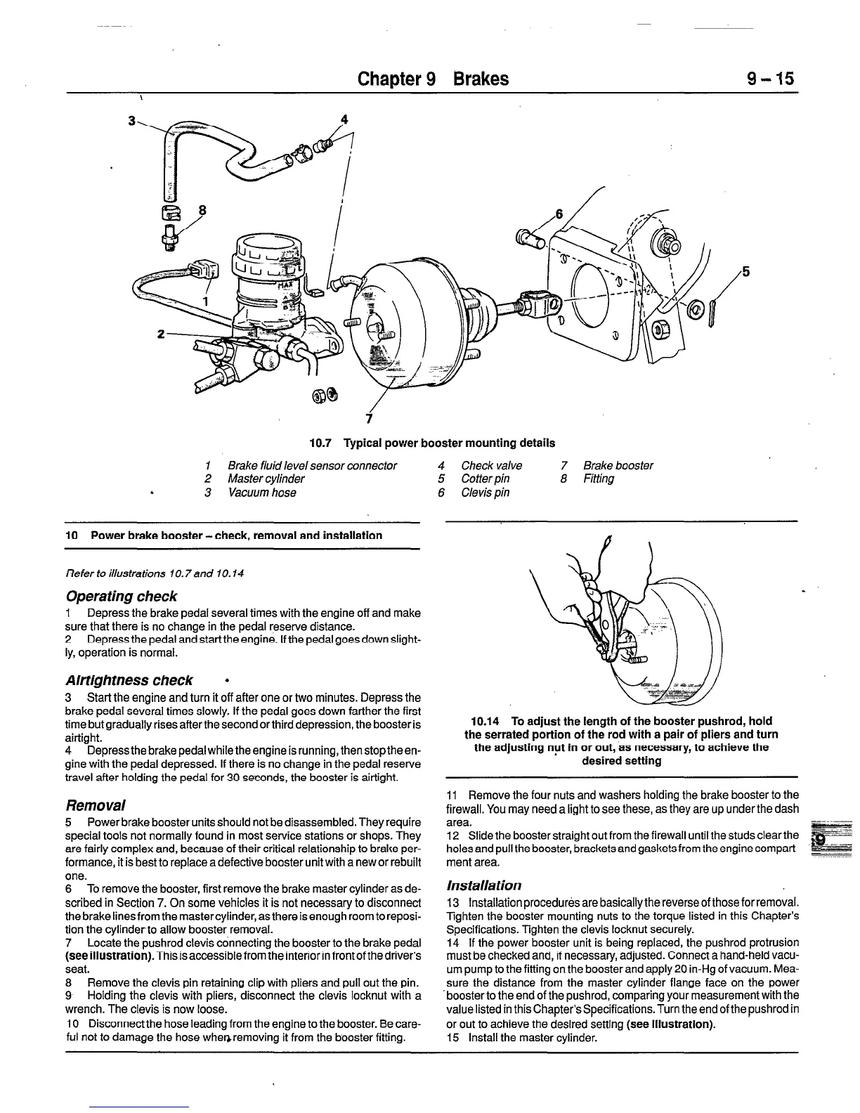
10.7 Typical power booster mounting details
1 Brake fluid level sensor connector 4 Check valve
2 Master cylinder 5 Cotter pin
.
3 Vacuum hose 6 Clevis pin
10 Power brake booster-check, removal and installation
Refer to illustrations 10.7and IO. 14
Operating check
1 Depress the brake pedal several times with the engine off and make
sure that there is no change in the pedal reserve distance.
2 Depress the pedal and start the engine. If the pedal goes down slight-
ly, operation is normal.
Airtigh tness check *
3 Start the engine and turn it off after one or two minutes. Depress the
brake pedal several times slowly. If the pedal goes down farther the first
time but gradually rises after the second or third depression, the booster is
airtight.
4 Depressthe brakepedalwhiletheengineisrunning, thenstoptheen-
gine with the pedal depressed. If there is no change in the pedal reserve
travel after holding the pedal for 30 seconds, the booster is airtight.
10.14 To adjust the length of the booster pushrod, hold
the serrated portion of the rod with a pair of pliers and turn
the adjusting nut in or out, as necessary, to achieve the
desired setting
Removal
5 Power brake booster units should not be disassembled. They require
special tools not normally found in most service stations or shops. They
are fairly complex and, because of their critical relationship to brake per-
formance, it is best to replace a defective booster unit with a new or rebuilt
one.
6 To remove the booster, first remove the brake master cylinder as de-
scribed in Section 7. On some vehicles it is not necessary to disconnect
the brake lines from the master cylinder, as there is enough room to reposi-
tion the cylinderto allow booster removal.
7 Locate the pushrod clevis connecting the booster to the brake pedal
(see illustration).This
is accessible from the interior in front of the driver’s
seat.
8 Remove the clevis pin retaining clip with pliers and pull out the pin.
9 Holding the clevis with pliers, disconnect the clevis locknut with a
wrench. The clevis is now loose.
10 Disconnectthe hose leading from the engine to the booster. Be care-
ful not to damage the hose whenremoving it from the booster fitting.
11 Remove the four nuts and washers holding the brake booster to the
firewall. You may need a light to see these, as they are up under the dash
area.
12 Slide the booster straight out from the firewall until the studs clear the
holes and pull the booster, bracketsand gaskets from the enginecompart-
ment area.
Installation
13 Installation procedures are basically the reverse of those for removal.
Tighten the booster mounting nuts to the torque listed in this Chapter’s
Specifications. Tighten the clevis locknut securely.
14 If the power booster unit is being replaced, the pushrod protrusion
must be checked and, if necessary, adjusted. Connect a hand-held vacu-
um pump to the fitting on the booster and apply 20 in-Hg of vacuum. Mea-
sure the distance from the master cylinder flange face on the power
‘booster to the end of the pushrod, comparing your measurement with the
value listed in this Chapter’s Specifications. Turn the end of the pushrod in
or out to achieve the desired setting
(see illustration).
15 Install the master cylinder.
7 Brake booster
8 Fitting
 Loading...


