Chapter 12 Chassis electrical system
12.le To remove the front lens, remove the two screws
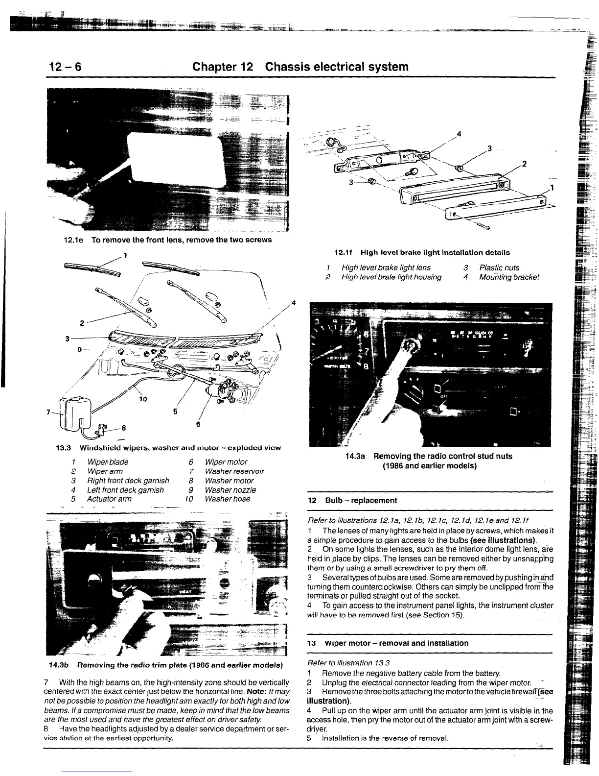
13.3 Windshield wipers, washer and motor-exploded view
1 Wipep blade 6 Wiper motor
2 Wiper arm 7 Washer reservoir
3 t?ight front deck garnish 8 Washer motor
4 Leti front deck garnish 9 Washer nozzle
5 Actuator arm 10 Washer hose
- _. -
“-- ~_~~ 1 _ I
.- 3
14.3b Removing the radio trim plate (1986 and earlier models)
7 With the high beams on, the high-intensity zone should be vertically
centered with the exact center lust below the horizontal line. Note: It may
not be possible to position the headlight aim exactly for both high and low
beams. If a compromise must be made, keep In mind that the low beams
are the most used and have the greatest effect on driver safety.
8 Have the headlights adjusted by a dealer setvice department or ser-
vice station at the earliest opportunity.
12.lf High-level brake light installation details
1
High level brake light lens
3 Plastic nuts
2 High level brale light housing 4 Mouhfing brackef
14.3a
Removing the radio control stud nuts
(1986 and earlier models)
12 Bulb - replacement
Refer to illusfrations 12. la, 72. lb, ~12. Ic, 12. Id, 72. le and 12. If
1 The lenses of many lights are held in place by screws, which makes it
a simple procedure to garn access to the bulbs (see illustrations).
2 On some lights the lenses, such as the interior dome light lens, a?e
held in place by clips. The lenses can be removed either by unsnapping
them or by using a small screwdriver to pry them off.
3 Several types of bulbs are used. Some are removed by pushing in&d
turning them counterclockwise. Others can simply be unclipped from the
terminals or pulled straight out of the socket.
4 To gain access to the instrument panel lights, the instrument cluster
will have to be removed first (see Section 15).
13 Wiper motor - removal and installation
Refer to illustration 13.3
7 Remove the negative battery cable from the battery.
2 Unplug the electrical connector leading from the wiper motor,
_
3 Remove the three bolts attaching the motorto the vehicle firewaqgee
illustration).
_~ _
4 Pull up on the wiper arm until the actuator arm joint is visible in the
access hole, then pry the motor out of the actuator arm joint with a screw-
driver,
5 Installation is the reverse of removal.
 Loading...


