Chapter 8 Clutch and driveline 8-7
Rear
2-joint type
23
Front
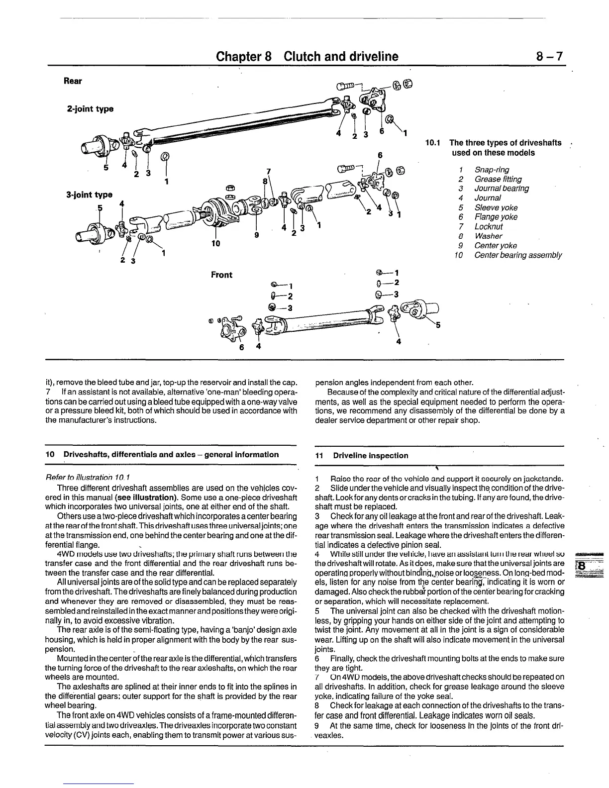
10.1 The three types of driveshafts .
used on these models
1 Snap-ring
2 Grease fitting
3 Journalbearing _
4 Journal
5 Sleeve yoke
6 Flange yoke
7 Locknut
8 Washer
9 Center yoke
10 Center bearing assembly
it), remove the bleed tube and jar, top-up the reservoir and install the cap.
7 If an assistant is not available, alternative ‘one-man’ bleeding opera-
tions can be carried out using a bleed tube equipped with aone-way valve
or a pressure bleed kit, both of which should be used in accordance with
the manufacturer’s instructions.
10 Driveshafts, differentials and axles-general information
Refer to illustratioi, f 0.1
Three different driveshaft assemblies are used on the vehicles cov-
ered in this manual (see illustration). Some use a one-piece driveshaft
which incorporates two universal joints, one at either end of the shaft.
Others use a two-piece driveshaftwhich incorporates a center bearing
attherearofthefrontshaft.Thisdriveshaftusesthree universaljoints;one
at the transmission end, one behind the center bearing and one at the dif-
ferential flange.
4WD models use two driveshafts; the primary shaft runs between the
transfer case and the front differential and the rear driveshaft runs be-
tween the transfer case and the rear differential.
All universal joints are of the solid type and can be replaced separately
from the driveshaft. The driveshafts are finely balanced during production
and whenever they are removed or disassembled, they must be reas-
sembled and reinstalled in the exact manner and positions they were origi-
nally in, to avoid excessive vibration.
The rear axle is of the semi-floating type, having a ‘banjo’ design axle
housing, which is held in proper alignment with the body by the rear sus-
pension.
Mounted in the center of the rear axle is the differential, which transfers
the turning force of the driveshaft to the rear axleshafts, on which the rear
wheels are mounted.
The axleshafts are splined at their inner ends to fit into the splines in
the differential gears; outer support for the shaft is provided by the rear
wheel bearing.
The front axle on 4WD vehicles consists of a frame-mounted differen-
tial assembly and two driveaxles. The driveaxles incorporate two constant
velocity (CV) joints each, enabling them to transmit power at various sus-
pension angles independent from each other.
Because of the complexity and critical nature of the differential adjust-
ments, as well as the special equipment needed to perform the opera-
tions, we recommend any disassembly of the differential be done by a
dealer service department or other repair shop.
11 Drlveline inspection
\
1 Raise the rear of the vehicle and support it securely on jackstands.
2 Slide under the vehicle and visually inspect the condition of the drive-
shaft. Lookforanydentsorcracksin the tubing. Ifanyarefound, thedrive-
shaft must be replaced.
3 Check for any oil leakage at the front and rear of the driveshaft. Leak-
age where the driveshaft enters the transmission indicates a defective
rear transmission seal. Leakage where the driveshaft enters the differen-
tial indicates a defective pinion seal.
4 While still under the vehicle, have an assistant turn the rear wheel so
the driveshaftwill rotate. As it does, make sure that the universal joints are
operating properly without bindjng,=noise or looseness. On long-bed mod-
els, listen for any noise from the center bearirg:indicating it is worn or
damaged. Also check the rubb& portion of the center bearing for cracking
or separation, which will necessitate replacement.
5 The universal joint can also be checked with the driveshaft motion-
less, by gripping your hands on either side of the joint and attempting to
twist the joint. Any movement at all in the joint is a sign of considerable
wear. Lifting up on the shaft will also indicate movement in the universal
joints.
6 Finally, check the driveshaft mounting bolts at the ends to make sure
they are tight.
7 On 4WD models, the above driveshaftchecks should be repeated on
all driveshafts. In addition, check for grease leakage around the sleeve
yoke, indicating failure of the yoke seal.
8 Check for leakage at each connection of thedriveshafts to the trans-
fer case and front differential. Leakage indicates worn oil seals.
9 At the same time, check for looseness ih the joints of the front dri-
veaxles.
 Loading...


