Chapter 8 Clutch and driveline
8-15
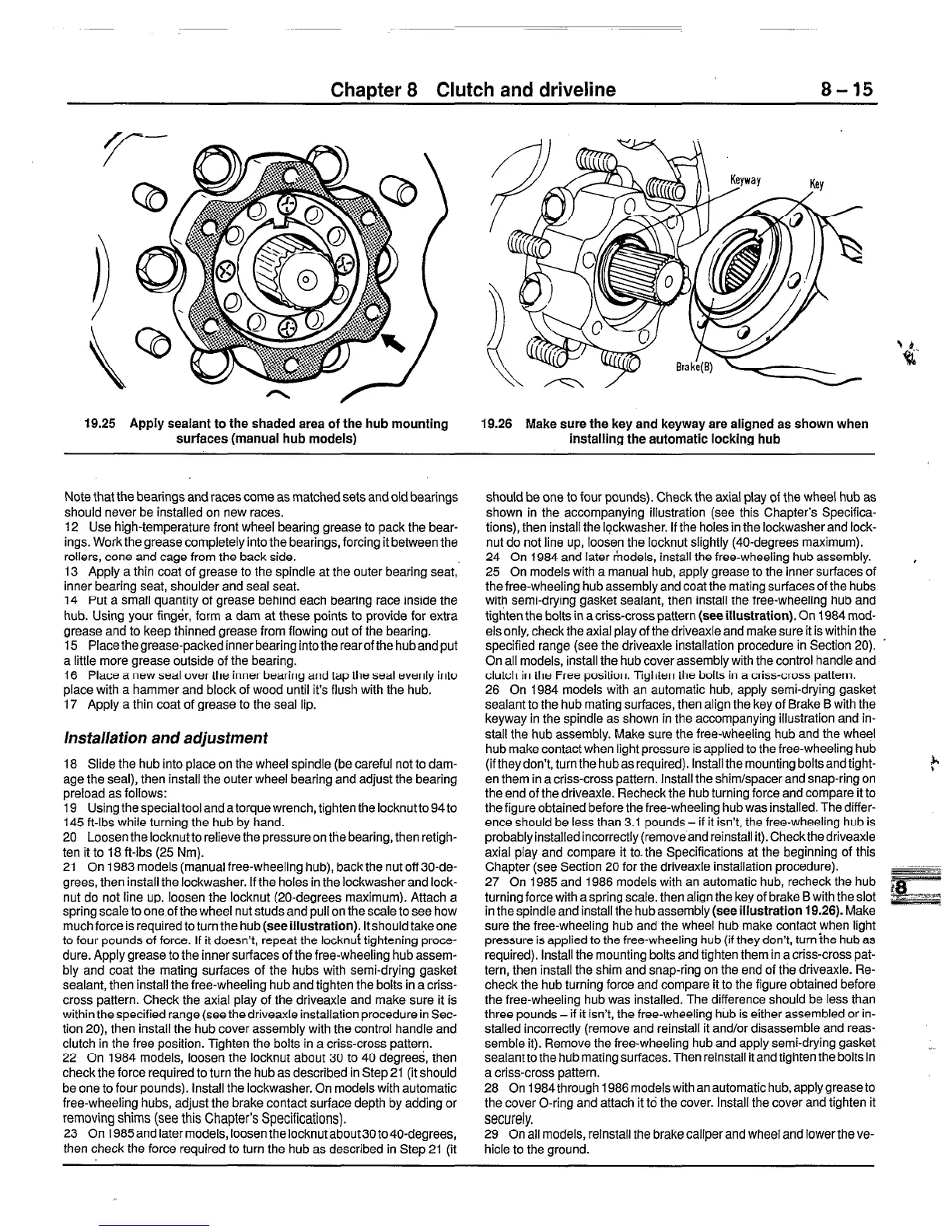
19.25 Apply sealant to the shaded area of the hub mounting
surfaces (manual hub models)
19.26 Make sure the key and keyway are aligned as shown when
installing the automatic locking hub
Note that the bearings and races come as matched sets and old bearings
should never be installed on new races.
12 Use high-temperature front wheel bearing grease to pack the bear-
ings. Work the grease completely into the bearings, forcing it between the
rollers, cone and cage from the back side.
13 Apply a thin coat of grease to the spindle at the outer bearing seat,
inner bearing seat, shoulder and seal seat.
14 Put a small quantity of grease behind each bearing race inside the
hub. Using your finger, form a dam at these points to provide for extra
grease and to keep thinned grease from flowing out of the bearing.
15 Placethegrease-packed inner bearing intothe rearofthe hubandput
a little more grease outside of the bearing.
16 Place a new seal over the inner bearing and tap the seal evenly into
place with a hammer and block of wood until it’s flush with the hub.
17 Apply a thin coat of grease to the seal lip.
Installation and adjustment
18 Slide the hub into place on the wheel spindle (be careful not to dam-
age the seal), then install the outer wheel bearing and adjust the bearing
preload as follows:
19 Using the special tool and a torque wrench, tighten the locknutto 94 to
145 ft-lbs while turning the hub by hand.
20 Loosen the locknutto relieve the pressure on the bearing, then retigh-
ten it to 18 ft-lbs (25 Nm).
21 On 1983 models (manual free-wheeling hub), backthe nut off 30-de-
grees, then install the lockwasher. If the holes in the lockwasher and lock-
nut do not line up, loosen the locknut (20-degrees maximum). Attach a
spring scale to one of the wheel nut studs and pull on the scale to see how
much force is required to turn the hub (see
illustration).
ltshould takeone
to four pounds of force. If it doesn’t, repeat the locknuf tightening proce-
dure. Apply grease to the inner surfaces of the free-wheeling hub assem-
bly and coat the mating surfaces of the hubs with semi-drying gasket
sealant, then install the free-wheeling hub and tighten the bolts in a criss-
cross pattern. Check the axial play of the driveaxle and make sure it is
within the specified range (see thedriveaxle installation procedure in Sec-
tion 20), then install the hub cover assembly with the control handle and
clutch in the free position. Tighten the bolts in a criss-cross pattern.
22 On 1984 models, loosen the locknut about 30 to 40 degrees, then
check the force required to turn the hub as described in Step 21 (it should
be one to four pounds). Install the lockwasher. On models with automatic
free-wheeling hubs, adjust the brake contact surface depth by adding or
removing shims (see this Chapter’s Specifications).
23 On 1985 and later models, loosen the locknut about 30 to40-degrees,
then check the force required to turn the hub as described in Step 21 (it
should be one to four pounds). Check the axial play of the wheel hub as
shown in the accompanying illustration (see this Chapter’s Specifica-
tions), then install the lockwasher. If the holes in the lockwasherand lock-
nut do not line up, loosen the locknut slightly (40-degrees maximum).
24 On 1984 and later models, install the free-wheeling hub assembly. ,
25 On models with a manual hub, apply grease to the inner surfaces of
the free-wheeling hub assembly and coat the mating surfaces of the hubs
with semi-drying gasket sealant, then install the free-wheeling hub and
tighten the bolts in a crisscross pattern (see
illustration).
On 1984 mod-
els only, check the axial play of the driveaxle and make sure it is within the
specified range (see the driveaxle installation procedure in Section 20). .
On all models, install the hub cover assembly with the control handle and
clutch in the Free position. Tighten the bolts in a criss-cross pattern.
26 On 1984 models with an automatic hub, apply semi-drying gasket
sealant to the hub mating surfaces, then align the key of Brake B with the
keyway in the spindle as shown in the accompanying illustration and in-
stall the hub assembly. Make sure the free-wheeling hub and the wheel
hub make contact when light pressure is applied to the free-wheeling hub
(if they don’t, turn the hub as required). Install the mounting bolts and tight-
?
en them in a criss-cross pattern. Install the shim/spacer and snap-ring on
the end of the driveaxle. Recheck the hub turning force and compare it to
the figure obtained before the free-wheeling hub was installed. The differ-
ence should be less than 3.1 pounds - if it isn’t, the free-wheeling hub is
probably installed incorrectly (removeand reinstall it). Checkthedriveaxle
axial play and compare it to. the Specifications at the beginning of this
Chapter (see Section 20 for the driveaxle installation procedure).
-..-
- 27 On 1985 and 1986 models with an automatic hub, recheck the hub
turning force with a spring scale, then align the key of brake B with the slot
in the spindle and install the hub assembly
(see illustration 19.26).
Make
sure the free-wheeling hub and the wheel hub make contact when light
pressure is applied to the free-wheeling hub (if they don’t, turn ihe hub as
required). Install the mounting bolts and tighten them in a criss-cross pat-
tern, then install the shim and snap-ring on the end of tl-ie driveaxle. Re-
check the hub turning force and compare it to the figure obtained before
the free-wheeling hub was installed. The difference should be less than
three pounds - if it isn’t, the free-wheeling hub is either assembled or in-
stalled incorrectly (remove and reinstall it and/or disassemble and reas-
semble it). Remove the free-wheeling hub and apply semi-drying gasket
sealantto the hub mating surfaces. Then reinstall it and tighten the bolts in
a criss-cross pattern.
28 On 1984 through 1986 models with an automatic hub, apply grease to
the cover O-ring and attach it to the cover. Install the cover and tighten it
securely.
29 On all models, reinstall the brake caliper and wheel and lowerthe ve-
hicle to the ground.
 Loading...


