Chapter 3 Cooling, heating and air conditioning systems
18.1 b 18.1 b Evaporator assembly Evaporator assembly
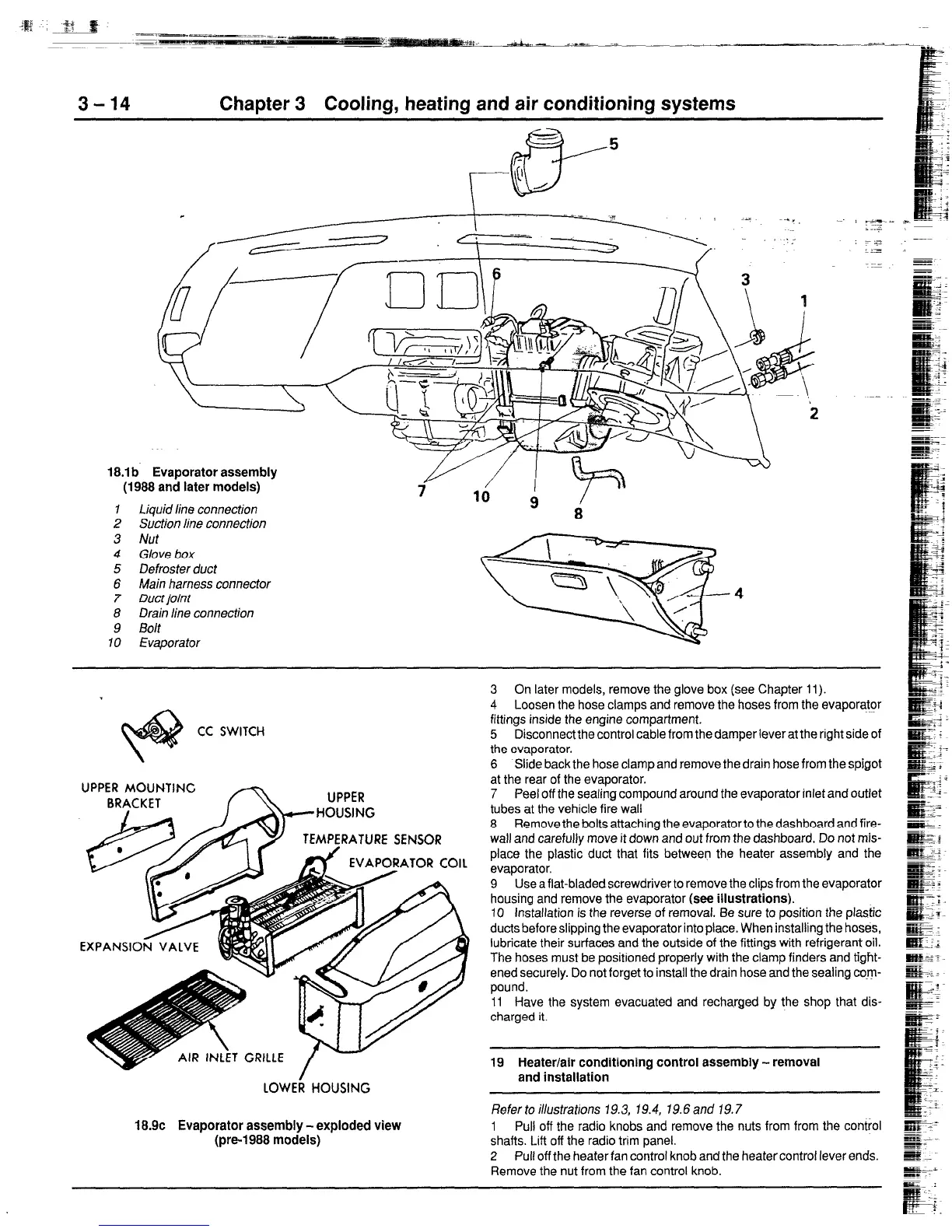
(1988 and later models) (1988 and later models)
1 1 Liquid line connection Liquid line connection
2 2 Suction line connection Suction line connection
3
Nut
4 Glove box
5 Defroster duct
6 Main harness connector
7 Duct joint
8 Drain line connection
9 Bolt
10 Evaporator
CC SWITCH
MOUNTING
TEMPERATURE SENSOR
EVAPORATOR COIL
UPPER
110
LOWEk HOUSING
18.9c Evaporator assembly - exploded view
(pre-1988 models)
3 On later models, remove the glove box (see Chapter 11).
4 Loosen the hose clamps and remove the hoses from the evaporator
fittings inside the engine compartment.
5 Disconnectthe control cable from the damper lever at the right side of
the evaporator.
6 Slide back the hose clamp and remove the drain hose from the spigot
at the rear of the evaporator.
7 Peel off the sealing compound around the evaporator inlet and outlet
tubes at the vehicle fire wall
8 Removethe boltsattachingtheevaporatortothedashboardandfire-
wall and carefully move it down and out from the dashboard. Do not mis-
place the plastic duct that fits between the heater assembly and the
evaporator.
9 Use a flat-bladedscrewdriver to remove the clips from the evaporator
housing and remove the evaporator
(see illustrations).
10 Installation is the reverse of removal. Be sure to position the plastic
ducts before slipping the evaporator into place. When installing the hoses,
lubricate their surfaces and the outside of the fittings with refrigerant oil.
The hoses must be positioned properly with the clamp finders and tight-
ened securely. Do not forget to install the drain hose and the sealing CX.~JI-
pound.
11 Have the system evacuated and recharged by the shop that dis-
charged it.
19 Heater/air conditioning control assembly - removal
and installation
Refertoillustrations 19.3, 19.4, 79.6and 19.7
1 Pull off the radio knobs and remove the nuts from from the control
shafts. Lift off the radio trim panel.
2 Pull off the heater fan control knob and the heatercontrol lever ends.
Remove the nut from the fan control knob.
 Loading...


