Chapter 6
Emissions control systems
6-7
17 Disconnectthepurge
hosefromtheaircleaner(seeillustration)and
blow into it. If the valve is not open, it is in good condition. Next, start the
engine and increase the engine speed to 1500 or 2000 rpm and blow into
the purge hose again. If the valve is open, it is operating properly.
18 Ifthevalvedoesnotcheckoutasdescribed,replaceitwithanewone.
Fuel check valve
19 The fuel check valve, located just to the left of the fuel tank, is de-
signedtoprevent fuelleaksshouldthevehiclerolloverdun’nganaccident.
The checkvalve contains two balls. Under normal conditions the gasoline
vapor passage in the valve is open, but if a roll-over occurs, either of the
two balls will close the fuel passage and prevent fuel leaks.
20 Remove the hose clamps and disconnect the hoses from the check
valve.
21 Remove the bolt attaching the fuel check valve to the rear body
mounting bracket.
22 Check the hoses for cracks and replace them if they are deteriorated.
23 Installation of the valve is the reverse of removal.
Two-way valve
Refer to illustration 3.27
24 The two-way valve, located just to the left of the fuel tank, is com-
posed of a pressure valve and a vacuum valve. The pressure valve is de-
signed to open when the fuel tank internal pressure has increased over the
normal pressure, which allows the fuel vapors to enter the charcoal canis-
terforstorage, and the vacuum valve opens when avacuum has been pro-
duced in the tank.
25 Removal of the valve is quite simple. Loosen the hose clampsand pull
off the two hoses, then remove the valve mounting bolt.
26 Blow lightly into the valve inlet. If there is an initial resistance followed
by passage of air, the valve is in good condition. Repeatthecheck by blow-
ing into the outlet.
27 Installation is the reverse of removal. The valve must tilt approximate-
ly 7-degrees (see illustration) in relation to the fuel tank when it is in-
stalled.
Vapor/liquid separator tank(s)
28 The function of the separator tank is to temporarily accommodate an
increased volume of gasoline caused by expansion at high outside air
temperatures. They also prevent liquid fuel from entering the vapor line
during hard cornering.
29 Mark each fuel/vapor hose and its corresponding fitting with num-
bered pieces of tape.
30 Refer to Chapter 4 and remove the fuel tank.
31 The separator tanks are attached to the top of the fuel tank. They can
be removed very easily once the fuel tank has been separated from the
vehicle.
32 Replace any crackld or deteriorated fuel/vapor hoses.
33 Installation is basically the reverse of removal. Chapter4 contains de-
tailed fuel tank installation procedures.
Purge control system (fuel-injected models only)
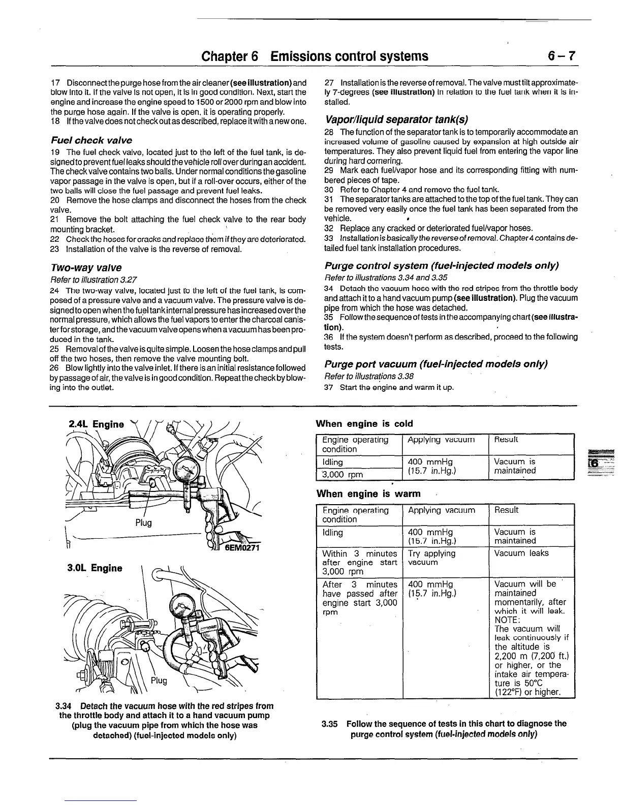
Refer to illustrations 3.34 and 3.35
34 Detach the vacuum hose with the red stripes from the throttle body
and attach it to a hand vacuum pump (see illustration). Plug the vacuum
pipe from which the hose was detached.
35 Follow the sequence of tests in the accompanying
chart(seeillustra-
tion).
36
If the system doesn’t perform as described, proceed to the following
tests.
Purge port vacuum (fuel-injected models only)
Refer to illustrations 3.38
37 Start the engine and warm it up.
3.34 Detach the vacuum hose with the red stripes from
the throttle body and attach it to a hand vacuum pump
(plug the vacuum pipe from which the hose was
detached) (fuel-injected models only)
When engine is cold
1 Engine operating
Applying vacuum
condition
Idling 400 mmHg
3,000 rpm
(15.7
in.Hg.)
.
When engine is warm
Result
Vacuum is
maintained
Engine operating Applying vacuum Result
condition
Idling
400 mmHg
Vacuum is
(15.7 in.Hg.)
maintained
Within 3 minutes Try applying Vacuum leaks
after engine start vacuum
3,000 rpm
After 3 minutes 400 mmHg Vacuum will be
have passed after (15.7 in.Hg.) maintained
engine start 3,000 momentarily, after
wm
which it will leak.
NOTE:
The vacuum will
leak continuously if
the altitude is
2,200
m (7,200 ft.)
or higher, or the
intake air tempera-
ture is 50°C
(122°F) or higher.
3.35
Follow the sequence of tests in this chart to diagnose the
purge
control system (fuel-injected models only)
 Loading...


