Chapter 6 Emissions control systems
Air control v&e
Blmetal
I
Temperature
sensor
--Au cleaner
- Intake manifold
vacuum
/
L
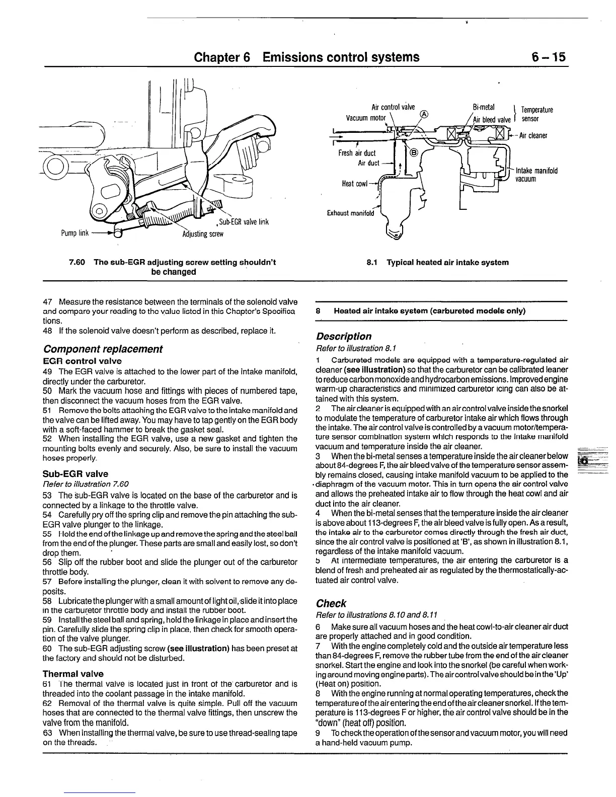
7.60 The sub-EGR adjusting screw setting shouldn’t 8.1 Typical heated air intake system
be changed
47 Measure the resistance between the terminals of the solenoid valve
and compare your reading to the value listed in this Chapter’s Specifica-
tions.
48 If the solenoid valve doesn’t perform as described, replace it.
Component replacement
EGR control valve
49 The EGR valve is attached to the lower part of the intake manifold,
directly under the carburetor.
50 Mark the vacuum hose and fittings with pieces of numbered tape,
then disconnect the vacuum hoses from the EGR valve.
51 Remove the bolts attaching the EGR valve to the intake manifold and
the valve can be lifted away. You may have to tap gently on the EGR body
with a soft-faced hammer to break the gasket seal.
52 When installing the EGR valve, use a new gasket and tighten the
mounting bolts evenly and securely. Also, be swre to install the vacuum
hoses properly.
Sub-EGR valve
Refer to ihsfrafion 7.60
53 The sub-EGR valve is located on the base of the carburetor and is
connected by a linkage to the throttle valve.
54 Carefully pry off the spring clip and remove the pin attaching the sub-
EGR valve plunger to the linkage.
55 Hold the end of the linkage up and remove the spring and the steel ball
from the end of the plunger. These parts are small and easily lost, so don’t
drop them. ’
56 Slip off the rubber boot and slide the plunger out of the carburetor
throttle body.
57 Before installing the plunger, clean it with solvent to remove any de-
posits.
58 Lubricate the plungerwith a small amount of light oil,slide it into place
in the carburetor throttle body and install the rubber boot.
59 Install the steel ball and spring, hold the linkage in place and insert the
pin. Carefully slide the spring clip in place, then check for smooth opera-
tion of the valve plunger.
60 The sub-EGR adjusting screw (see illustration) has been preset at
the factory and should not be disturbed.
Thermal valve
61 The thermal valve is located just in front of the’carburetor and is
threaded into the coolant passage in the intake manifold.
62 Removal of the thermal valve is quite simple. Pull off the vacuum
hoses that are connected to the thermal valve fittings, then unscrew the
valve from the manifold.
63 When installing the thermal valve, be sure to use thread-sealing tape
on the threads.
8 Heated air intake system (carbureted models only)
Description
Refer to illustration 8.1
1 Carbureted models are equipped with a temperature-regulated air
cleaner (see illustration) so that the carburetor can be calibrated leaner
to reducecarbon monoxideand hydrocarbon emissions. Improvedengine
warm-up characteristics and minimized carburetor icing can also be at-
tained with this system.
2 The air cleaner is equipped with an air control valve inside the snorkel
to modulate the temperature of carburetor intake air which flows through
the intake. The air control valve is controlled by a vacuum motor/tempera-
ture sensor combination system which responds to the intake manifold
vacuum and temperature inside the air cleaner.
3 When the bi-metal senses a temperature inside the air cleaner below
about 84-degrees F, the air bleed valve of the temperature sensor assem-
bly remains closed, causing intake manifold vacuum to be applied to the
#diaphragm of the vacuum motor. This in turn opens the air control valve
and allows the preheated intake air to flow through the heat cowl and air
duct into the air cleaner.
4 When the bi-metal senses that the temperature inside the air cleaner
is above about 113-degrees F, the air bleed valve is fully open. As a result,
the intake air to the carburetor comes directly through the fresh air duct,
since the air control valve is positioned at ‘B’, as shown in illustration 8.1,
regardless of the intake manifold vacuum.
5 At intermediate temperatures, the air entering the carburetor is
a
blend of fresh and preheated air as regulated by the thermostatically-ac-
tuated air control valve.
Check
Refer to ihsfrafions 8.70 and 8.11
6 Make sure all vacuum hoses and the heat cowl-to-air cleaner air duct
are properly attached and in good condition.
7 With the engine completely cold and the outside air temperature less
than 84-degrees F, remove the rubber tube from the end of the air cleaner
snorkel. Start the engine and look into the snorkel (be careful when work-
ingaroundmoving engineparts).TheaircontrolvalveshouId bein the’llp’
(Heat on) position.
8 With the engine running at normal operating temperatures, check the
temperatureoftheairenteringtheendoftheaircleanersnorkel. Ifthetem-
perature is 113-degrees For higher, the air control valve should be in the
“down” (heat off) position.
9 To check the operation of the sensor and vacuum motor, you will need
a hand-held vacuum pump.
 Loading...


