6-16 Chapter 6 Emissions control systems
8.10 To check the temperature sensor for the heated air intake
system, apply vacuum to the sensor-the air control valve should
be in the “up” (heat on) position
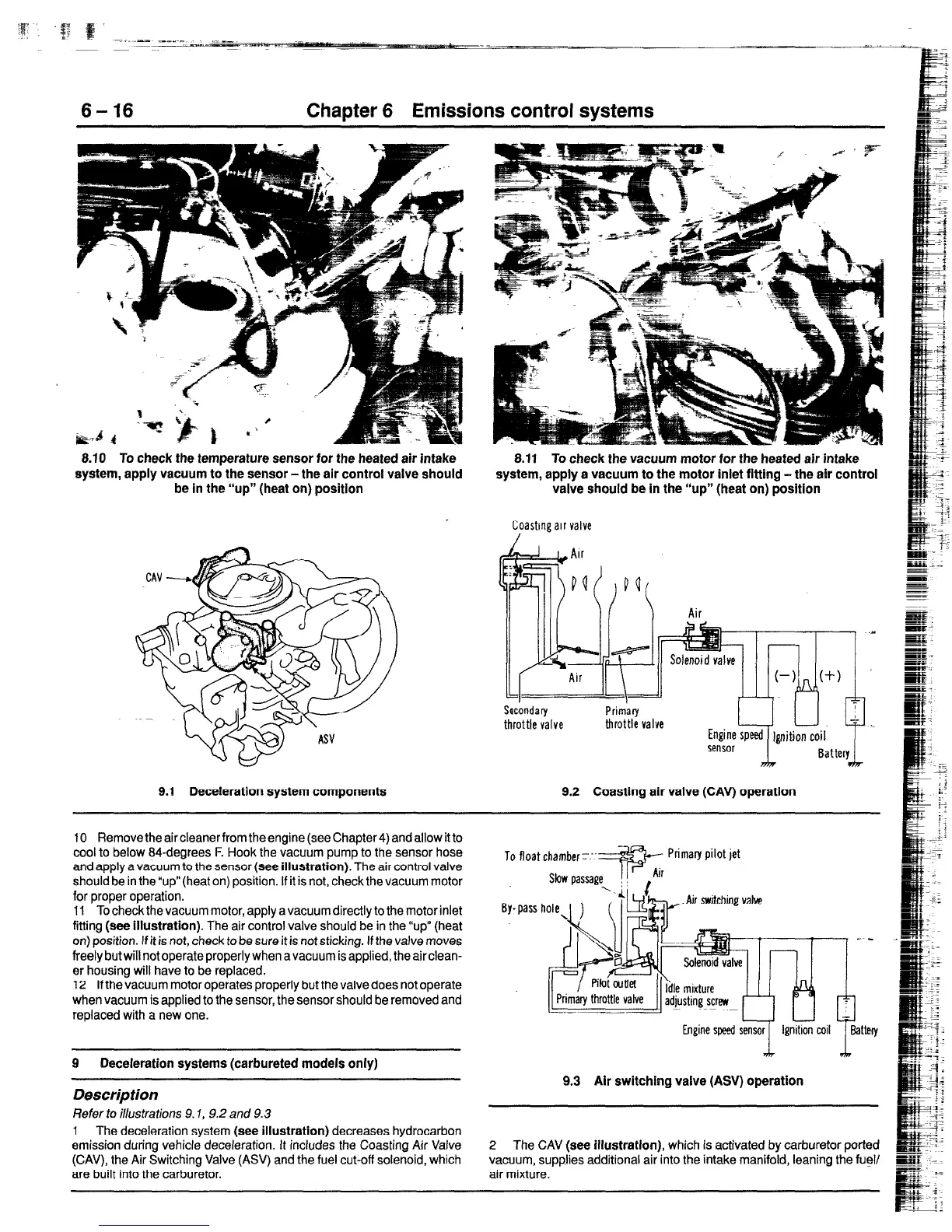
9.1 Deceleration system components
8.11 To check the vacuum motor for the heated air intake
system, apply a vacuum to the motor inlet fitting -the air control
valve should be in the “up“ (heat on) position
Coasting air valve
/
9.2 Coasting air valve (CAV) operatlon
10 Remove the air cleaner from the engine (see Chapter 4) and allow it to
cool to below 84-degrees F. Hook the vacuum pump to the sensor hose
and apply a vacuum to the sensor
(see illustration).
The air control valve
should be in the “up” (heat on) position. If it is not, check the vacuum motor
for proper operation.
11 To check the vacuum motor, apply a vacuum directly to the motor inlet
fitting
(see illustration).
The air control valve should be in the “up” (heat
on) position. If it is not, check to be sure it is
not
sticking. If the valve moves
freely but wiIl not operate properly when a vacuum is applied, the air clean-
er housing will have to be replaced.
12 If the vacuum motor operates properly but the valve does not operate
when vacuum is applied to the sensor, the sensor should be removed
and
replaced with a new one.
To float chamber-:.
9
Deceleration systems (carbureted models only)
Description
Refer to illustrations 9.7, 9.2 and 9.3
1 The deceleration system
(see illustration)
decreases hydrocarbon
emission during vehicle deceleration. It includes the Coasting Air Valve
(CAV), the Air Switching Valve (AS/) and the fuel cut-off solenoid, which
are built into the carburetor.
9.3 Air switching valve (ASV) operation
2
The CAV
(see illustration),
which is activated by carburetor ported
vacuum, supplies additional air into the intake manifold, leaning the fuel/
air mixture.
 Loading...


