4-10 Chapter 4
Fuel and exhaust systems
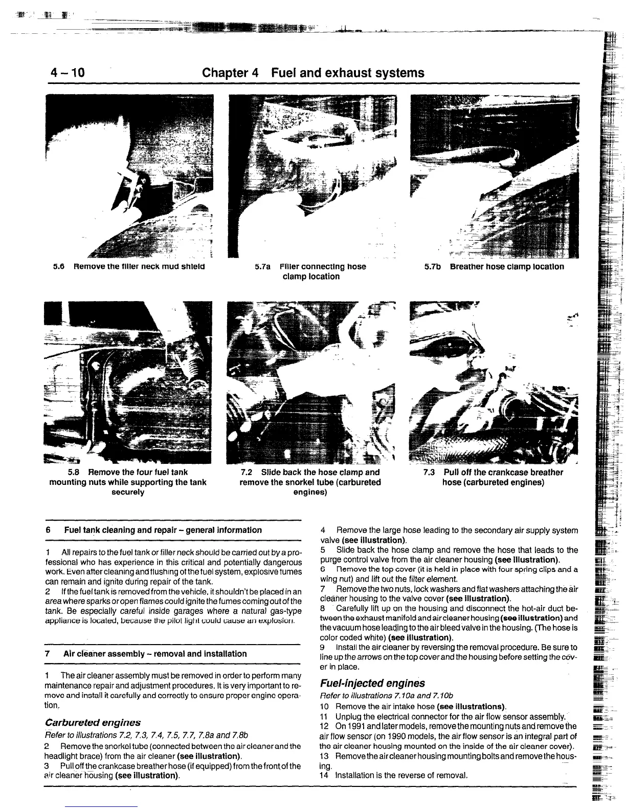
5.6 Remove the filler neck mud shield
5.8 Remove the four fuel tank
mounting nuts while supporting the tank
securely
5.7a Filler connecting hose
clamp location
7.2 Slide back the hose clamp and
remove the snorkel tube (carbureted
engines)
6 Fuel tank cleaning and repair - general information
1 All repairs to the fuel tank or filler neck should be carried out by a pro-
fessional who has experience in this critical and potentially dangerous
work. Even after cleaning and flushing of the fuel system, explosive fumes
can remain and ignite during repair of the tank.
2 If the fuel tank is removed from the vehicle, it shouldn’t be placed in an
area where sparks oropen flames could ignite the fumes coming out of the
tank. Be especially careful inside garages where a natural gas-type
appliance is located, because the pilot light could cause an explosion.
7 Air cieaner assembly - removal and installation
1 The air cleaner assembly must be removed in order to perform many
maintenance repair and adjustment procedures. It is very important to re-
move and instafl it carefully and correctly to ensure proper engine opera-
tion,
(farbureted engines
&fertoi//usfrafions7.2, 7.3, 7.4, 7.5, 7.7, 7.8aand7.8b
2 Remove the snorkel tube (connected between the aircleanerand the
headlight brace) from the air cleaner (see illustration).
3 Pull off the crankcase breather hose (if equipped) from the front of the
air cleaner housing (see illustration).
5.7b Breather hose clamp location
7.3 Pull off the crankcase breather
hose (carbureted engines)
4 Remove the large hose leading to the secondary air supply system
valve (see illustration).
5 Slide back the hose clamp and remove the hose that leads to the
purge control valve from the air cleaner housing (see illustration).
6 Remove the top cover (it is held in place with four spring clips
and
a
wing nut) and lift out the filter element.
7 Remove the two nuts, lock washers and flat washers attaching the air
cleaner housing to the valve cover (see illustration).
8 Carefully lift up on the housing and disconnect the hot-air duct be-
tween the exhaust manifold and aircleaner housing (see illustration) and
the vacuum hose leading to the air bleed valve in the housing. (The hose is
color coded white) (see illustration).
9 Install the air cleaner by reversing the removal procedure. Be sure to
line up the arrows on the top coverand the housing before setting the cov-
er in place.
Fuel-injected engines
Refer to i//u.sfrafions 7.1 Oa and 7. lob
10 Remove the air intake hose (see illustrations).
11 Unplug the electrical connector for the air flow sensor assembly.
12 On 1991 and later models, remove the mounting nuts and remove the
air flow sensor (on 1990 models, the air flow sensor is an integral part of
the air cleaner housing mounted on the inside of the air cleaner cover).
13 Remove the air cleaner housing mounting bolts and remove the hous-
ing.
14 Installation is the reverse of removal.
 Loading...


