Chapter 4 Fuel and exhaust systems ’
4-21
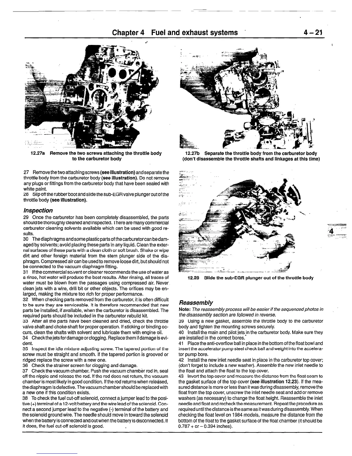
12.27a Remove the two screws attaching the throttle body
to the carburetor body
27 Remove thetwo attaching screws (see illustration) and separate the
throttle body from the carburetor body (see illustration). Do not remove
any plugs or fittings from the carburetor body that have been sealed with
white paint.
28 Slipoff therubberbootandslidethesub-EGRvalveplungeroutofthe
throttle body (see illustration).
Inspection
29 Once the carburetor has been completely disassembled, the parts
should be thoroughly cleaned and inspected. There are many commercial
carburetor cleaning solvents available which can be used with good re-
sults.
30 Thediaphragmsandsomeplasticpartsofthecarburetorcan bedam-
aged by solvents; avoid placing these parts in any liquid. Clean the exter-
nal surfaces of these parts with a clean cloth or soft brush. Shake or wipe
dirt and other foreign material from the stem plunger side of the dia-
phragm. Compressed air can be used to remove loose dirt, but should not
be connected to the vacuum diaphragm fitting.
31 If the commercial solvent or cleaner recommends the use of water as
a rinse, hot water will produce the best results. After rinsing, all traces of
water must be blown from the passages using compressed air. Never
clean jets with a wire, drill bit or other objects. The orifices may be en-
larged, making the mixture too rich for proper performance.
32 When checking parts removed from the carburetor, it is often difficult
to be sure they are serviceable. It is therefore recommended that new
parts be installed, if available, when the carburetor is disassembled. The
required parts should be included in the carburetor rebuild kit.
33 After all the parts have been cleaned and dried, check the throttle
valve shaft and choke shaft for proper operation. If sticking or binding oc-
curs, clean the shafts with solvent and lubricate them with engine oil.
34 Checkthejetsfordamageorclogging. Replacethemifdamageisevi-
dent.
35 Inspect the idle mixture adjusting screw. The tapered portion of the
screw must be straight and smooth. If the tapered portion is grooved or
ridged replace the screw with a new one.
36 Check the strainer screen for clogging and damage.
37 Check the vacuum chamber. Push the vacuum chamber rod in, seal
off the nipple and release the rod. If the rod does not return, the vacuum
chamber is most likely in good condition. If the rod returns when rel&j.sed,
the diaphragm is defective. The vacuum chamber should be replaced with
a new one if this condition exists.
38 To check the fuel cut-off solenoid, connect a jumper lead to the posi-
tive (+) terminal of a 12-volt battery and the wire lead of the solenoid. Con-
nect a second jumper lead to the negative (-) terminal of the battery and
the solenoid ground wire. The needle should move in toward the solenoid
when the battery is connected and out when the battery is disconnected. If
it does, the fuel cut-off solenoid is good.
12.27b Separate the throttle body from the carburetor body
(don’t disassemble the throttle shafts and linkages at this time)
12.28 Slide the sub-EGR plunger out of the throttle body
Reassembly
Note:
The reassembly process will be easier if the sequencedphotos in
the disassembh section are
fqllowed
in reverse.
39 Using a new gasket, assemble the throttle body to the carburetor
body and tighten the mounting screws securely.
40 install the main and pilot jets in the carburetor body. Make sure they
are installed in the correct bores.’
41 Place the anti-overflow ball in place in the bottom of the float bowl and
insert the accelerator pump steel check ball and weight into the accelera-
tor pump bore.
42 Install the new inlet needle seat in place in the carburetor top cover;
(don’t forget to include a new washer). Assemble the new inlet needle to
the float and attach the float to the top cover.
43 Invert the top cover and measure the distance from the float seam to
the gasket surface of the top cover (see illustration 12.23). If the mea-
sured distance is more or less than it was during disassembly, remove the
float from the top cover, unscrew the inlet needle seat and add or remove
washers (as necessary) to change the float height. Reassemble the inlet
needle and float and recheck the measurement. Repeat the procedure as
required until the distance is the same as it was during disassembly. When
checking the float level on 1984 models, measure the distance from the
bottom of the float to the gasket surface of the float chamber (it should be
0.787 + or - 0.394 inches).
 Loading...


