Chapter 4 Fuel and exhaust systems
4-23
Truck with A, T and with .
M/‘T for federal
Truck with M T for
13.19 Throttle opener (idle-up) adjusting screw location (air-conditioned models)
16 If the idle speed changes, return it to the specified rpm by turning the
SAS in or out as necessary.
17 If the engine misfires badly, repeat the procedure, turning the MAS
further counterclockwise initially.
Air-conditiqned models
Refer to illustration 13:19
18 Afterthe idle mixtureandspeed have been adjusted, an additionalad-
justment must be made to all air-conditioned models.
19 Turn off all accessories. Put the transmission in Neutral and apply the
parking brake. If the vehicle has power steering, put the wheels in the
straight ahead position so the power steering pump isn’t loaded. Now turn
the air conditioner control switch to On (this activates the throttle opener
on the carburetor). Adjust the idle speed to the idle-up engine speed listed
in this Chapter’s Specifications by turning the throttle opener (idle-up) ad-
justing screw
(see illustration)
in or
out as necessary.
20 When the speed has been set, turn off th& air conditioner control
switch-the engine should return to the specified idle speed.
Automatic choke
21 The choke valve is automatically operated by a wax element that
senses the coolant temperature. This element allows the choke valve to
close under spring pressure at low coolant temperatures and opens it
throughaset leverandarackandpiniongearsetupas thecoolanttemper-
ature increases.
22 The wax element plunger pushes against an adjustable screw on the
choke set lever; This screw is preset at the factory to provide for proper
chokeclosing and opening and sealed with white paint. Do nottamperwith
it, as choke operation will be adversely affected.
23 The choke should not require any adjustment as long as the rack and
pinion gears are properly oriented and the choke pinion gear assembly is
adjusted so that the choke plate is lightly seated in the closed position
when the choke linkage is installed.
14 Carburetor (FBC) (1985 and 1986 models) -overhaul
Warning:
Gasoline
is
extreme/y flammable, so take extra precautions
when you work on any part of the fuel system. Don’t smoke or allow open
flames or bare light bulbs near the work area, and don’t work in a garage
where a naturalgas-type appliance (such as awaterheaterorclothes dry-
er) with a pilot light is present If you spill any fuel on your skin, rinse it off
immediately with soap and water.
When you perform any kind of work on
the fuel system, wear safety glasses and
have a Class B type fire exfin-
guisher on hand.
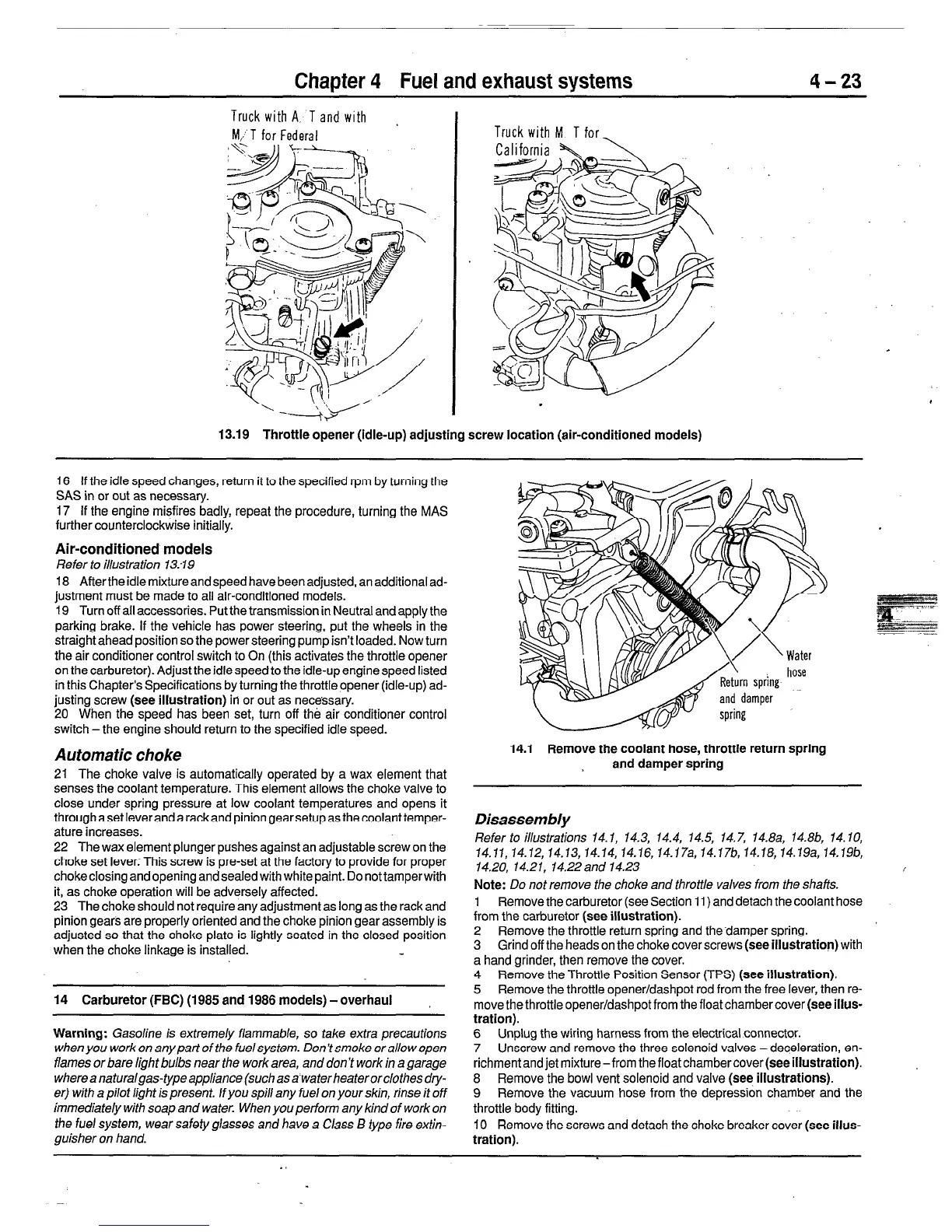
14.1 Remove the coolant hose, throttle return spring
and damper spring
Disassembly
Refer to illustrations 14.1, 14.3, 14.4, 14.5, 14.7, 14.8a, 14.8b, 14.10,
14.11,14.12,14.13, 14.14, 14.16, 14.17a,14.17b,14.16,14.19a,14.19b,
14.20, 14.21, 14.22and 14.23
i
Note: Do not remove the choke and throttle valves from the shafts.
1 Remove the carburetor (see Section 11) and detach the coolant hose
from the carburetor (see
illustration).
2 Remove the throttle return spring and the-damper spring.
3 Grind off the heads on the choke cover screws
(see illustration)
with
a hand grinder, then remove the cover.
4 Remove the Throttle Position Sensor (TPS) (see
illustration).
5 Remove the throttle opener/dashpot rod from the free lever, then re-
move the throttle opener/dashpot from the float chamber cover
(see illus-
tration).
6 Unplug the wiring harness from the electrical connector.
7
Unscrew and remove the three solenoid valves -deceleration, en-
richmentandjet mixture-from thefloatchambercover(seeillustration).
8 Remove the bowl vent solenoid and valve
(see illustrations).
9
Remove the vacuum hose from the depression chamber and the
throttle body fitting.
IO Remove the screws and detach the choke breaker cover
(see illus-
tration).
.
 Loading...


