1-24 Chapter 1 Tune-up and routine maintenance
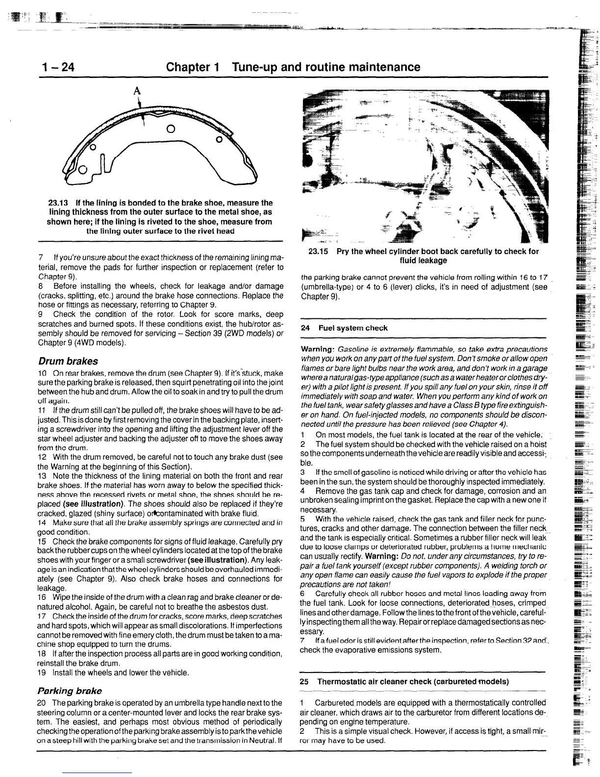
23.13 If the lining is bonded to the brake shoe, measure the
lining thickness from the outer surface to the metal shoe, as
shown here; if the lining is riveted to the shoe, measure from
the lining outer surface to the rivet head
7 If you’re unsure about the exact thickness of the remaining lining ma-
terial, remove the pads for further inspection or replacement (refer to
Chapter 9).
8 Before installing the wheels, check for leakage and/or damage
(cracks, splitting, etc.] around the brake hose connections. Replace the
hose or fittings as necessary, referring to Chapter 9.
9 Check the condition of the rotor. Look for score marks, deep
scratches and burned spots. If these conditions exist, the hub/rotor as-
sembly should be removed for servicing - Section 39 (2WD models) or
Chapter 9 (4WD models).
Drum brakes
10 On rear brakes, remove the drum (see Chapter 9). If it’sstuck, make
sure the parking brake is released, then squirt penetrating oil into the joint
between the hub and drum. Allow the oil to soak in and try to pull the drum
off again.
11 If the drum still can’t be pulled off, the brake shoes will have to be ad-
justed. This is done by first removing the cover in the backing plate, insert-
ing a screwdriver into the opening and lifting the adjustment lever off the
star wheel adjuster and backing the adjuster off to move the shoes away
from the drum.
12 With the drum removed, be careful not to touch any brake dust (see
the Warning at the beginning of this Section).
13 Note the thickness of the lining material on both the front and rear
brake shoes. If the material has worn away to below the specified thick-
ness above the recessed rivets or metal shoe, the shoes should be re-
placed (see illustration). The shoes should also be replaced if they’re
cracked, glazed (shiny surface) okontaminated with brake fluid.
14 Make sure that all the brake assembly springs are connected and in
good condition.
15 Check the brake components for signs of fluid leakage. Carefully pry
back the rubber cups on the wheel cylinders located at the top of the brake
shoes with your finger or a small screwdriver (see illustration). Any leak-
age is an indication that the wheel cylinders should be overhauled immedi-
ately (see Chapter 9). Also check brake hoses and connections for
leakage.
16 Wipe the inside of the drum with a clean rag and brake cleaner or de-
natured alcohol. Again, be careful not to breathe the asbestos dust.
17 Check the inside of the drum for cracks, score marks, deep scratches
and hard spots, which will appear as small discolorations. If imperfections
cannot be removed with fine emery cloth, the drum must be taken to a ma-
chine shop equipped to turn the drums.
18 If after the inspection process all parts are in good working condition,
reinstall the brake drum.
19 Install the wheels and lower the vehicle.
Parking brake
20 The parking brake is operated by an umbrella type handle next to the
steering column or a center-mounted lever and locks the rear brake sys-
tem. The easiest, and perhaps most obvious method of periodically
checkingtheoperationof the parking brake assemblyistoparkthevehicle
on a steep hill with the parking brake set and the transmission in Neutral. If
23.15 Pry the wheel cylinder boot back carefully to check for
fluid leakage
the parking brake cannot prevent the vehicle from rolling within 16 to 17
(umbrella-type) or 4 to 6 (lever) clicks, it’s in need of adjustment (see
Chapter 9).
24 Fuel system check
Warning: Gasoline is extremely flammable, so take extra precautions
when you work on any part of the fuel system. Don’t smoke or a/low open
flames or bare light bulbs near the work area, and don? work in a garage
whereanaturalgas-typeapp/iance(suchasa waterheaterorclothesdry-
e@ with a pilot light is present. /f you spill any fuel on your skin, rinse it off
immediate/y with soap and water. When you perform any kind of work on
the fuel tank, wearsafetyglasses and have a C/ass B type fire extinguish-
er on hand. On fuel-injected mode/s, no components should be discon-
nected until the pressure has been relieved (see Chapter 4).
1 On most models, the fuel tank is located at the rear of the vehicle.
2 The fuel system should be checked with the vehicle raised on a hoist
so the components underneath thevehicle are readily visible and accessi-
ble.
3 If the smell of gasoline is noticed while driving or after the vehicle has
been in the sun, the system should be thoroughly inspected immediately.
4 Remove the gas tank cap and check for damage, corrosion and an
unbroken sealing imprint on the gasket. Replace the capwith a new one if
necessary.
5 With the vehicle raised, check the gas tank and filler neck for punc-
tures, cracks and other damage. The connection between the filler neck
and the tank is especially critical. Sometimes a rubber filler neck will leak
due to loose clamps or deteriorated rubber, problems a home mechanic
can usually rectify. Warning: Do not, underanycircumstances, try to re-
pair a fuel tank yourself (except rubber components). A welding torch or
any open flame can easily cause the fuel vapors to explode if the proper
precautions are not taken!
6 Carefully check all rubber hoses and metal lines leading away from
the fuel tank. Look for loose connections, deteriorated hoses, crimped
linesandotherdamage. Followthelinestothefrontofthevehicle,careful-
ly inspecting them all the way. Repair or replace damaged sections as nec-
essary.
7 If a fuel odor is still evident after the inspection, refer to Section 32 and-
check the evaporative emissions system.
25 Thermostatic air cleaner check (carburetedmodels)
1 Carbureted models are equipped with a thermostatically controlled
air cleaner, which draws air to the carburetor from different locations de-
pending on engine temperature.
2 This is a simple visual check. However, if access is tight, a small mir-
ror may have to be used.
 Loading...


