2A-14 Chapter 2 Part A 2.6L four-cylinder engim
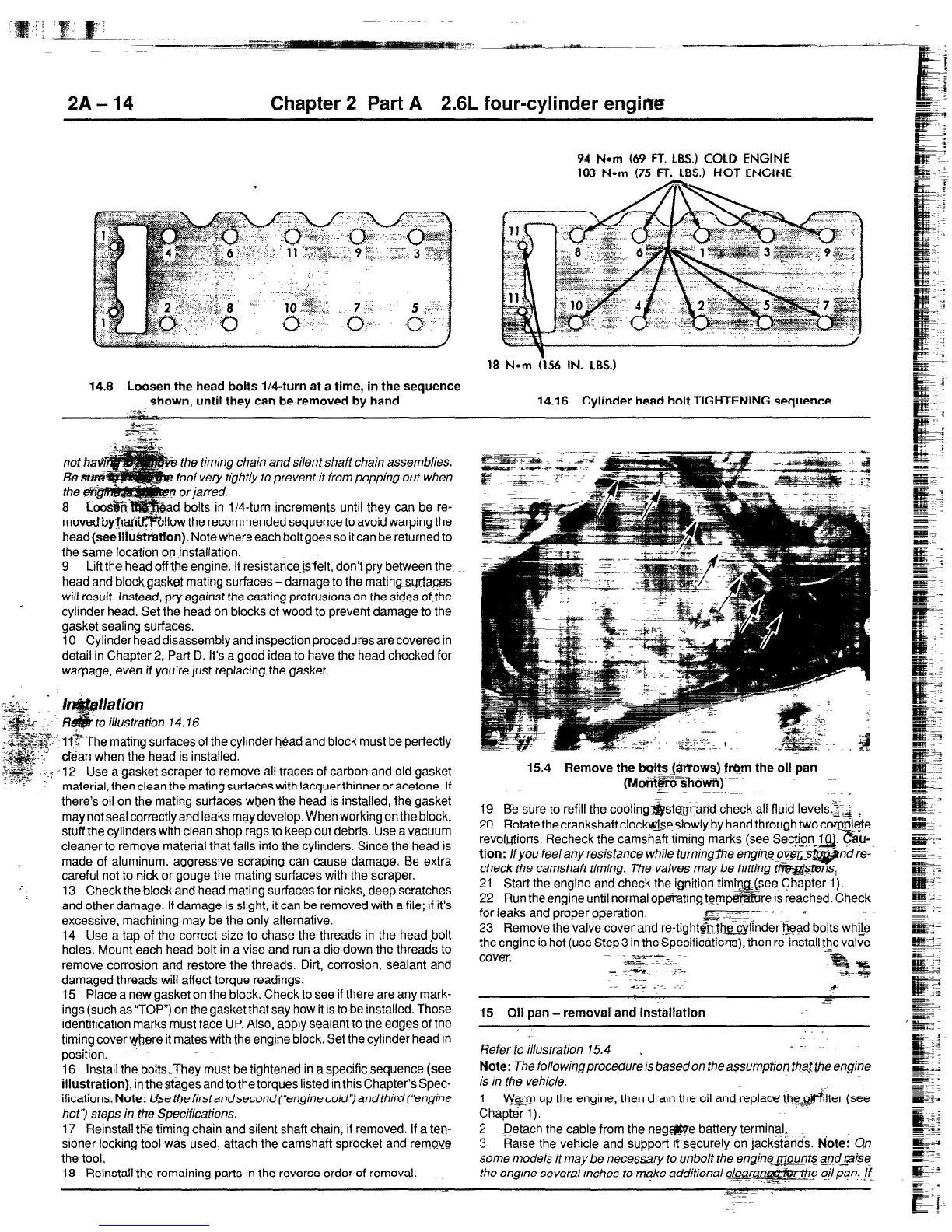
94
Nom (69 FT. LBS.) COLD ENGINE
103 Nom (75 FT. LBS.) HOT ENGINE
18 Nom 056 IN. LBS.)
14.8 Loosen the head bolts IM-turn at a time, in the sequence
shown, until they can be removed by hand 14.16 Cylinder head bolt TIGHTENING sequence
s..?zy.
q-x
n and silent shaft chain assemblies.
lo prevent it from popping out when
m increments until they can be re-
nded sequence to avoid warping the
head
(see ilh&tration).
Note where each bolt goes so it can be returned to
the same location on installation.
9 Lift the head off the engine. If resistan~,&?elt, don’t pry between the
head and blockgasket mating surfaces-damage to the matingsurfaces
will result. Instead, pry against the casting protrusions on the sides of,the
cylinder head. Set the head on blocks of wood to prevent damage to the
gasket sealing surfaces.
10 Cylinder head disassembly and inspection procedures are covered in
detail in Chapter 2, Part D. It’s a good idea to have the head checked for
warpage, even if you’re just replacing the gasket.
.
.&XT
_ _I c
;;j$$i- ,,:
w&
‘fr’.
f the cylinder head and block must be perfectly
‘?” &an when the head is installed.
s”.g~c+i;
z;$yg , -:
i 12 Use a gasket scraper to remove all traces of carbon and old gasket
x
material, then clean the mating surfaces with lacquer thinner or acetone. If
there’s oil on the mating surfaces when the head is installed, the gasket
may not seal correctly and leaks may develop. When working on the block,
stuff the cylinders with clean shop rags to keep out debris. Use a vacuum
cleaner to remove material that falls into the cylinders. Since the head is
made of aluminum, aggressive scraping can cause damage. Be extra
careful not to nick or gouge the mating surfaces with the scraper.
13 Check the block and head mating surfaces for nicks, deep scratches
and other damage. If damage is slight, it can be removed with a file; if it’s
excessive, machining may be the only alternative.
14 Use a tap of the correct size to chase the threads in the head bolt
holes, Mount each head bolt in a vise and run a die down the threads to
remove corrosion and restore the threads. Dirt, corrosion, sealant and
damaged threads will affect torque readings.
15 Place a new gasket on the block. Check to see if there are any mark-
ings (such as “TOP”) on the gasket that say how it is to be installed. Those
identification marks must face UP. Also, apply sealant to the edges of the
timing cover where it mates with the engine block. Set the cylinder head in
position.
16 install the boltsThey must be tightened in a specific sequence (see
illustration),
in the stages and to the torques listed in this Chapter’s Spec-
ifications.
Note:
Use thefirstandsecond(“enginecold’~and third (‘engine
hof’) steps in ttre Specifications.
17 Reinstall the timing chain and silent shaft chain, if removed. If a ten-
sioner locking tool was used, attach the camshaft sprocket and remove
the tool.
18 Reinstall the remaining parts in the reverse order of removal:
15.4 Remove the b&s (@Vows) ft@m the oil pan
(Morit~-3~3.Vi)-~=
i. __~~.__
.~.
19 Be sure to refill the cooling~st~and check all fluid leveis.~$ I_
20 Rotate the crankshaft clock@se slowly by hand through twocon$ete
revol.utions. Recheck the camshaft timing marks (see Sect@n-a.
a-u-
tion:
/f you fee/ any resistance while turningfhe engifle b/E-
check the camshaft timing. The valves may be hitting
21 Start the engine and check the ignition tim@-g(see Chapter 1).
22 Run the engine until normal opeFatingtempe@&re is reached. Check
for leaks and proper operation.
it>:---=- ...’ ”
me.: ~.I~ -:
23 Remove the valve cover and re-tight&+t.&&ylinder i$ad bolts whL&
the engine is hot (use Step 3 in the Specifications), then re-install the valve
cover
--- ~~
= -+-a. -..A..
%
-. _ _~
a%
15 Oil pan - removal and installation
Refer to illustration 15.4 ~
Note:
The following procedure is based on the assumption tha.j the engine
is in the veh/cie.
-7
1 Wg up the engine, then drain the oil and replaci?the$‘?ilter (see
Chapterl).
2 Detach the cable from the neg@&e battery terminal,
3 Raise the vehicle and support itsecurely on jackstands.
Note: On
some models it may be necessary to unbolt the engine&q$$ a_nd-@se
the engine several Inches to make additional e ai/ pan. jr ,-__
.--_-
 Loading...


