.-
-..._ rr~-. ._ -~
T*
i;;
tt;;.
W
Chapter 2 Part A 2.6L four-cylinder engine 2A- 15
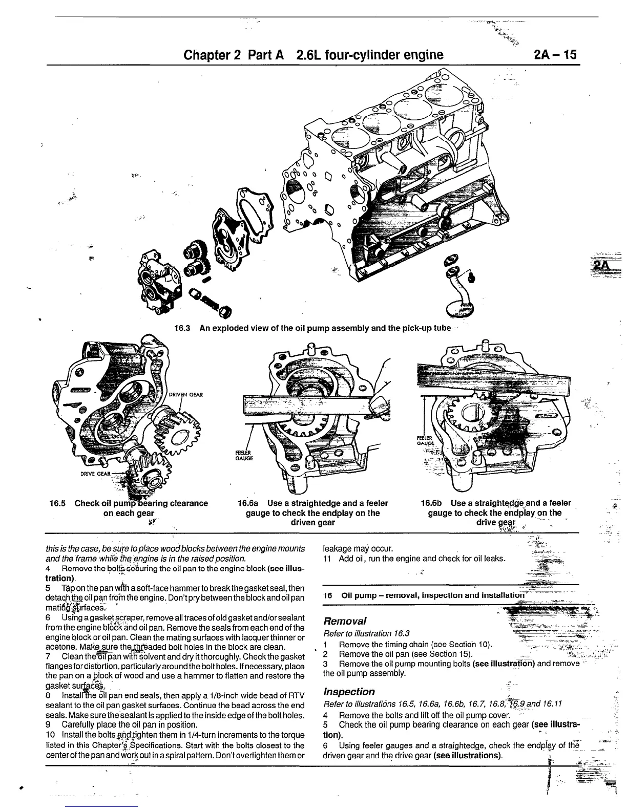
16.3 An exploded view of the oil pump assembly and the pick-up tube
16.5 Check oil pu
on each gear
#P’ ._
ghtedge and a feeler
gauge to check the endplay on the
driven gear
16.6b Use a straightq$geT,and a feeler
gauge to check the endplay,?tthe
drive !g&. c _ =
-..
.A%
.I
this Hhe case, be .sj&e top/ace woodblocks between the engine mounts
and the frame whil& th$iqngine is in the raisedposition.
4 Remove the bol$~seEuring the oil pan to the engine block (see illus-
tration).
5 Tap on the pan wih a soft-face hammer to break the gasket seal, then
detac@,t& oil pan ffo”m the engine. Don’t pry between the block and oil pan
matiQ&Qfaces~ ’
6 Us&g agasket scraper, remove all traces of old gasket and/orsealant
from the engine bl%&ind oil pan. Remove the seals from each end of the
engine block or oil pan. Clean the mating surfaces with lacquer thinner or
acetone. Make&e the&@aded bolt holes in the block are clean.
7 Clean them pan with @Ivent and dry it thoroughly. Check the gasket
flangesfordist@on, particularly around the bolt holes. If necessary, place
the pan on aplock of wood and use a hammer to flatten and restore the
gasket su c&. .’
8 lnstal % e o”n pan end seals, then apply a i/8-inch wide bead of RTV
sealant to the oil pan gasket surfaces. Continue the bead across the end
seals. Make sure ihe’sealant is applied to the inside edge of the bolt holes.
9 Carefully place the oil pan in position.
10 Install the boltsqp$ighten them in l/4-turn increments to the torque
listed in this Chapter@pecifications. Start with the bolts closest to the
centerofthepanandworkout inaspiralpattern. Dontovertighten themor
.._
leakage maj, occur.
11 Add oil, run the
16 Oil pump - removal, inspection and installatiozV I~-=-~---
m .:=F-
* T.
Removal
L++ :z:
Refer to illustration 16.3
--_ .L -<&. . -_
z- ---. _.
Tz.;=7ia-.
1 Remove the timing chain (see Section 10). )_I -..&g;;:, ..I
2 Remove the oil pan (see Section 15).
;“x-Fi ., .
,.i,,_:.. .,.I;!‘::;
3 Remove the oil pump mounting bolts (see illustration) and remove ‘~
the oil pump assembly.
Inspection
Refer to illustrafidns 16.5, 16.6a, 16.6bb, 16.7, 16.&@and 16.1 I
4 Remove the bolts and lift off the oil pump cover.
5 Check the oil pump bearing clearance on each gear (see illustra-
tion).
- /
6 Using feeler gauges and a straightedge, check the endpigy of th%-
driven gear and the drive gear (see illustrations).
b.
 Loading...


