Chapter 2 Part A 2.6L four-cylinder engine
2A-19
.
.
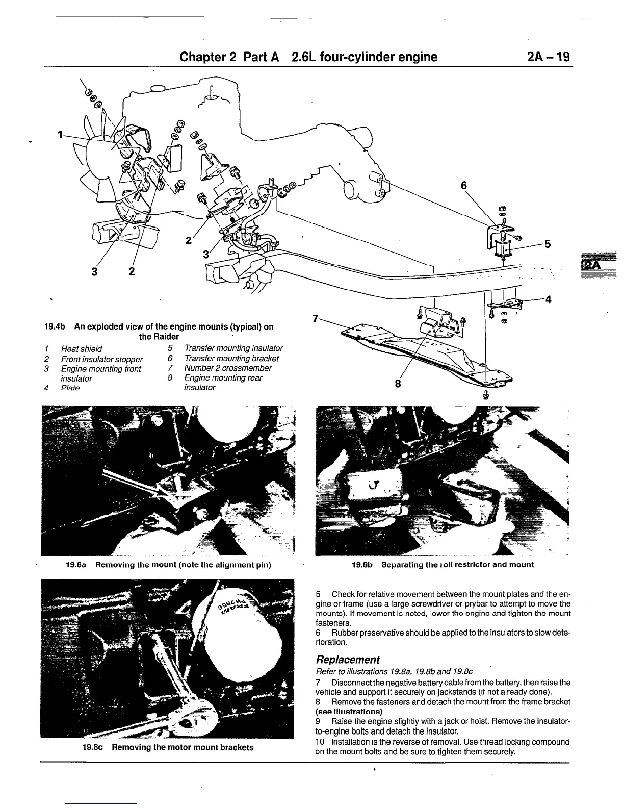
19.4b An exploded view of the engine mounts (typical) on
the Raider
1
Heat shield
5 Transfer mounting insulator
2 Front insulator stopper
6 Transfer mounting bracket
3 Engine mounting front
7 Number 2 crossmember
insulator
8 Engine mounting rear
4 Plate
insulator
19.8c Removing the motor mount brackets
19.8a Removing the mount (note the alignment pin)
19.8b
Separating the roll restrictor and mount
5 Check for relative movement between the mount plates and the en-
gine or frame (use a large screwdriver or prybar to attempt to move the
mounts). If movement is noted, lower the engine and tighten the mount
fasteners.
6 Rubber preservative should be applied to theinsulators to slow dete-
rioration.
Replacement
Refer to illustrations 19.8a, 19.8b and 19.8~
7 Disconnect the negative battery cable from the battery, then raise the
vehicle and support it securely on jackstands (if not already done).
8 Remove the fasteners and detach the mount from the frame bracket
(see illustrations).
9 Raise the engine slightly with a jack or hoist. Remove the insulator-
to-engine bolts and detach the insulator.
IO Installation is the reverse of removal. Use thread locking compound
on the mount bolts and be sure to tighten them securely.
 Loading...


