Chapter 7 Part B Automatic transmission
7B-3
I
L2D@R P
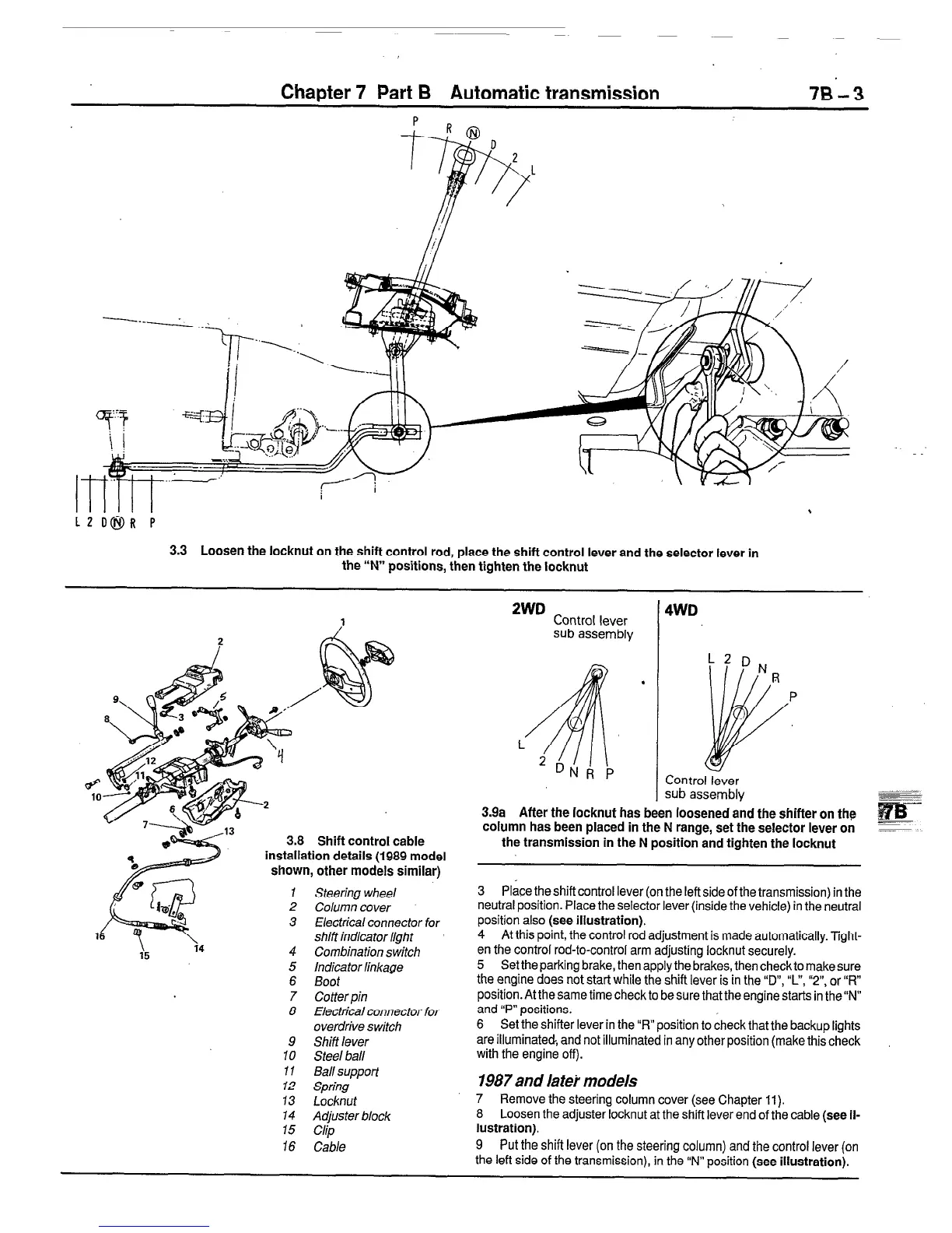
3.3 Loosen the locknut on the shift control rod, place the shift control lever and the selector lever in
the “N” positions, then tighten the locknut
3.8 Shift control cable
installation details (1989 model
shown, other models similar)
I Steering wheel
2
Column cover
3 Electrical connector
for
shift indicator light
9
10
11
12
13
14
15
16
Combination switch
Indicator linkage
Boot
Cotter pin
Electrical connector for
overdrive switch
Shift lever
Steel ball
Ball support
Spring
Locknut
Adjuster block
Clip
Cable
2WD
Control lever
4WD
sub assembly
.
P
L
I
Control lever
sub assembly
3.9a After the locknut has been loosened and the shifter on the
column has been placed in the N range, set the selector lever on
-
the transmission in the N position and tighten the locknut
3 Place the shift control lever (on the left side of the transmission) in the
neutral position. Place the selector lever (inside the vehicle) in the neutral
position also (see illustration).
4 At this point, the control rod adjustment is made automatically. Tight-
en the control rod-to-control arm adjusting locknut securely.
5 Set the parking brake, then apply the brakes, then check to make sure
the engine does not start while the shift lever is in the “D”, “c’, “2”, or “R”
position. At the same time check to be sure that the engine starts in the “N”
and “P” positions.
6 Set the shifter lever in the “FL” position to check that the backup lights
are illuminated, and not illuminated in any other position (make this check
with the engine off).
1987 and IateL models
7 Remove the steering column cover (see Chapter 11).
8 Loosen the adjuster locknut at the shift lever end of the cable (see il-
lustration).
9 Put the shifi lever (on the steering column) and the control lever (on
the left side of the transmission), in the “N” position (see illustration).
 Loading...


