7B-4 Chapter 7 Part B Automatic transmission
53.3-53.7 (2.098-2.114)
Nut
mm (in.)
Lhoke
vntve
Lam
Throttle
lever
3.10 if necessary, adjust the length of the
indicator needle linkage
Throttle rod C
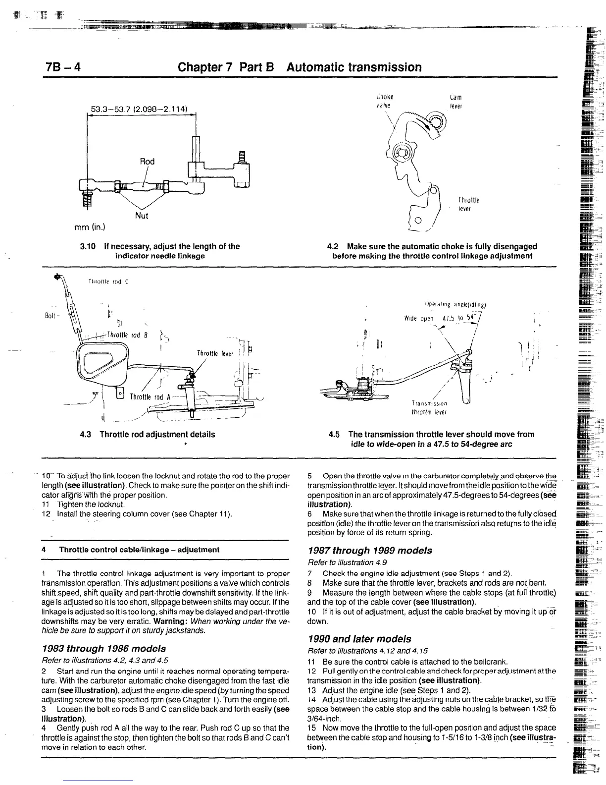
4.2 Make sure the automatic choke is fully disengaged
before making the throttle control linkage adjustment
4.3 Throttle rod adjustment details 4.5 The transmission throttle lever should move from
‘
idle to wide-open in a 47.5 to 54-degree arc
iU~- To $icfjust the link loosen the locknut and rotate the rod to the proper
length (see illustration). Check to make sure the pointer on the shift indi-
cator afigns v&h the proper position.
ii Tighten the locknut.
12 Install the steering column cover (see Chapter 11).
4 Throttle control cable/linkage - adjustment
1 The throttle control linkage adjustment is very important to proper
transmission operation. This adjustment positions a valve which controls
shift speed, shift quality
and
part-throttle downshift sensitivity. If the link-
ageis adjusted so it is too short, slippage between shifts may occur. if the
linkage is adjusted so it is too long, shifts may be delayed and part-throttle
downshifts may be very erratic. Warning: When working under the ve-
hicle be sure to support it on sturdy jackstands.
1983 through 1986 models
Refer to illustrations 4.2, 4.3 and 4.5
2 Start and run the engine until it reaches normal operating tempera-
ture. With the carburetor automatic choke disengaged from the fast idle
cam (see illustration), adjust the
engine
idle
speed (by turning the speed
adjusting screw to the specified rpm (see Chapter 1). Turn the engine off.
3 Loosen the bolt so rods B and C can slide back and forth easily (see
illustration).
4 Gently push rod A all the way to the rear. Push rod C up so that the
throttle is against the stop, then tighten the bolt so that rods Band C can’t
move in relation to each other.
5 Open the throttle valve In
the
carburetor completelyand qbs_erve the
transmissionthrottle k+er. It should move from the idle position to the wide
open position in an arcof approximately 47.5-degrees to 54-degrees&e
illustration).
6 Make sure that when the throttle linkage is returned to the fully clbsed
positton (idle) the throttle fever on the transmissioti also retu[ns to the idle
position by force of Its return spring.
1987 through 1989 models
Refer fo illustration 4.9
7 Check the engine idle adjustment (see Steps 1 and 2).
8 Make sure that the throttle lever, brackets and rods are not bent.
9 Measure the length between where the cable stops (at full throtile)
and the top of the cable cover (see illustration).
10 If it is out of adjustment, adjust the cable bracket by moving it up o’r
down.
1990 and later models
Refer to illustrations 4.12 and 4.15
11 Be sure the control cable
is
attached to the bellcrank.
12 Pull gently on the control cable and check for proper adjustment at the
transmission in the idle position (see illustration).
13 Adjust the engine idle (see- Steps 1 and 2).
14 Adjust the cable using the adjusting nuts on the cable bracket, so the
space between the cable stop and the cable housing is between i/32 t0
3J64-inch.
15 Now move the throttle to the full-open position and adjust the space
between the cable stop and housing to l-5/1 6 to l-3/8 fnch (see iliustra-
-.
tion).
 Loading...


