Chapter 7 Part B Automatic transmission 70-7
,7.9 Hold the adjusting screw still while tightening the locknut
2 Loosen the adjusting screw locknut and back it off five turns. Check
the adjusting screw to make sure it turns freely. Lubricate it if necessary.
3 Tighten theadjusting screw to the torque listed in thischapter’sspec-
ifications.
4 Back the adjusting screw off the number of turns listed in this Chap-
ter’s Specifications. Hold the adjusting screw at that point and tighten the
locknut.
Low/Reverse band
5 The low/reverse band is accessible after removing the transmission
oil pan (see illustrations). The band should be adjusted at the same time
the transmission fluid and filter is changed (see Chapter 1).
6 After the oil pan has been removed (see Chapter l), loosen the ad-
justing screw locknut.
7 Tighten the adjusting screw to the torque listed in this Chapter’s Spec-
ifications.
8 Back the adjusting screw out the number of turns listed in this Chap-
ter’s Specifications.
9 Hold the adjusting screw with a wrench so it can’t turn (see illustra-
tion), then tighten the locknut to the torque listed in this Chapter’s Specifi-
cations.
10 Install the transmission oil pan and bring the fluid to the proper level
(see Chapter 1). .
8 Automatic transmission - removal and installation
Refer to illustration 8.6, 8.1 la and 8.1 lb
Removal
1
Disconnect the negative cable from the battery.
2 If you’re working on a 4WD model, remove the knob from the transfer
case shift lever.
3 Raise the vehicle and support it securely on jackstands.
4 Drain the transmission fluid (see Chapter l), then reinstall the pan.
5 Remove the torque converter cover.
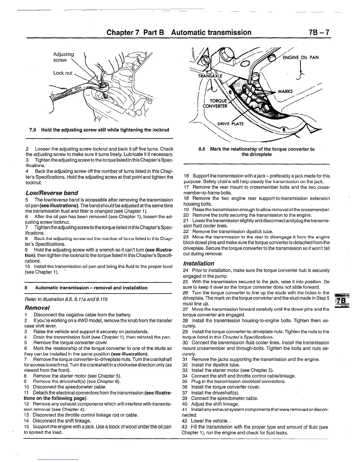
6 Mark the relationship of the torque converter to one of the studs so
theycan be installed in the same position (see illustration).
7 Remove the torque converter-to-driveplate nuts. Turn the crankshaft
foraccesstoeach nui.Turn thecrankshaftin aclockwisedirection only (as
viewed from the front).
8 Remove the starter motor (see Chapter 5).
9 Remove the driveshaft (see Chapter 8).
10 Disconnect the speedometer cable.
11 Detach the electrical connectors from the transmission (see illustra-
tions on the following page).
12 Remove any exhaust components which will interfere with transmis-
sion removal (see Chapter 4).
13 Disconnect the throttle control linkage rod or cable.
14 Disconnect the shift linkage.
15 Support the engine with a jack. Use a block of wood under the oil pan
to spread the load.
8.6 Mark the relationship of the torque converter to
the driveplate
16 Support the transmission with a jack- preferably a jack made for this
purpose. Safety chains will help steady the transmission on the jack.
17 Remove the rear mount to crossmember bolts and the two cross-
member-to-frame bolts.
18 Remove the two engine rear support-to-transmission extension
housing bolts.
19 Raise the transmission enough to allow removal of the crossmember.
20 Remove the bolts securing the transmission to the engine.
21 Lowerthetransmission slightlyanddisconnectandplug thetransmis-
sion fluid cooler lines.
22 Remove the transmission dipstick tube.
23 Move the transmission to the rear to disengage it from the engine
blockdowel pins and make sure the torque converter is detached from the
driveplate. Secure the torque converter to the transmission so it won’t fall
out during removal.
Ins talla tion
24 Prior to installation, make sure the torque converter hub is securely
engaged in the pump.
25 With the transmission secured to the jack, raise it into position. Be
sure to keep it level so the torque converter does not slide forward.
26 Turn the torque converter to line up the studs with the holes in the
driveplate. The mark on the torque converter and the stud made in Step 5
must line up.
27 Move the transmission forward carefully until the dowel pins and the
torque converter are engaged.
28 Install the transmission housing-to-engine bolts. Tighten them se-
curely.
29 Install the torque converter-to-driveplate nuts. Tighten the nuts to the
torque listed in this Chapter’s Specifications.
30 Connect the transmission fluid cooler lines. Install the transmission
mount crossmember and through-bolts. Tighten the bolts and nuts se-
curely.
31 Remove the jacks supporting the transmission and the engine.
32 Install the dipstick tube.
33 Install the starter motor (see Chapter 5).
34 Connect the shift and throttle control cable/linkage.
35 Plug in the transmission electricaltconnectors.
36 Install the torque converter cover.
37 Install the driveshaft(
39 Connect the speedometer cable.
40 Adjust the shift linkage.
41 Install any exhaust system components that were removed or discon-
nected.
42 Lower the vehicle. ‘.
43
Fill
the transmission
with the
proper type
and amount of fluid (see
Chapter l), run the engine and check for fluid leaks.
 Loading...


