(46-7/8)
1190
(39)
990
N
(48-25/32)
1239
(40-29/32)
1039
M
ø12.7(1/2)
mm(in.)
(35-7/16)
(27-9/16)
(41-3/4)
(33-7/8)
(47-1/4)
(39-3/8)
(39-3/8)
(31-1/2)
(41-3/4)
(33-7/8)
(47-3/16)
(39-5/16)
(45-3/8)
(37-1/2)
(43-5/16)
(35-7/16)
ø6.35(1/4)
900 952 998 860
9
800 1000 860
7
700
20
24
L
900
K
9
J
1060
HG
1200
F
1000
E
11
D
1060
C
1100
B
1152
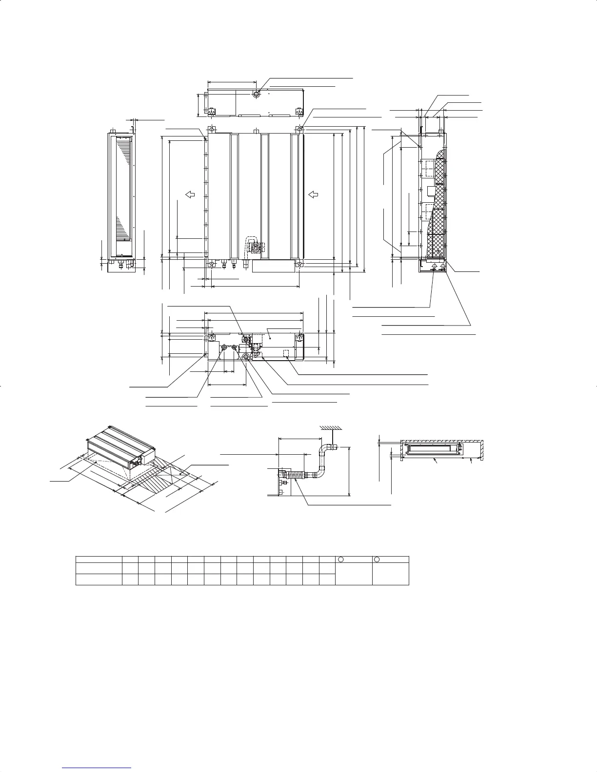
PEA-A12AA
PEA-A18AA
Model A
1198
Gas pipe Liquid pipe
1
2
Note1.Use M10 screw for the suspension bolt (field supply).
2.Keep the service space for the maintenance at the bottom.
3.This chart indicates for PEA-A12AA model,which has 2 fans.
PEA-A18AA models have 4 fans.
4.In case an inlet duct is used,remove the air filter(supply with
the unit), then install the filter(field supply) at suction side.
Drain pipe(O.D.ø32(1-1/4))
Terminal block (Remote controller transmission line)
Terminal block (Indoor/outdoor connecting line)
2
Refrigerant piping
flare connection (liquid)
Drain pipe(O.D.ø32(1-1/4))
(Emergency draining)
Knockout hole
ø
27(1-3/32)
(Remote controller transmission line)
Knockout hole
ø
27(1-3/32)
(Indoor/outdoor connecting line)
L-ø2.9(1/8)
2X2-ø2.9(1/8)
2XE-ø2.9(1/8)
Control box
Air filter
Suspension bolt hole
4-14X30(9/16X1-3/16) Slot
Refrigerant piping
flare connection (gas)
1
Drain pipe(O.D.ø32(1-1/4))
(Spontaneous draining)
Air
inlet
Air
outlet
N
M
57(2-1/4)
57(2-1/4)
159(6-9/32)
345(13-19/32)
(3-9/16)
(5-29/32)
(2-25/32)(4-19/32)
70
10 (13/32)
(3-15/16)
(1-15/16) (24-5/8)
37(1-15/32)
200(7-7/8)
H
20(13/16)
157.5 (6-7/32)
20 (13/16)
100 (3-15/16)
37(1-15/32)
12(1/2)
12(1/2)
88(3-15/32)
100(3-15/16)XJ=K
100(3-15/16)
88(3-15/32)
10 (13/32)
49
25 (1)
170(6-23/32)
102(4-1/32)
270(10-21/32)
116
150(Duct)
23(29/32)
100
25(1)
700(27-9/16)
677(26-21/32)
23 (29/32)
C
B (Suspension bolt pitch)23(29/32)
A
90
625 (Suspension bolt pitch)
D (Duct)
30(1-3/16)
100(3-15/16)X(E-1)=F
100(3-15/16)
20(13/16)
15(19/32)
(1-31/32 ~ 5-29/32)
(30-19/32)
(17-23/32)
(11-13/16)
(17-23/32)
More than 300
450
777
50
(1-31/32)
50 ~ 150
50(1-31/32)
G
450
Note2
Access door
Required space for service and maintenance
More than 20
More than 10
(13/16)
(13/32)
Access door
Ceiling surface
Make the access door at the appointed position
properly for service maintenance.
175±5(6-29/32±7/32)
Less than 300
Less than 550
(11-13/16)
(21-21/32)
Drain hose (I.D.ø32(1-1/4))
<accessory>
(Actual length)
 Loading...