41
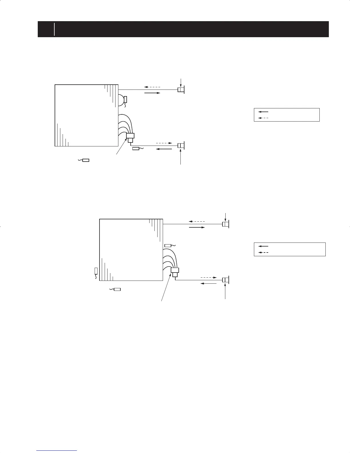
REFRIGERANT SYSTEM DIAGRAM
6
6-1. INDOOR UNIT
PLA-A·BA PCA-A·KA PEA-A·AA PEAD-A·AA
Thermistor TH2
Pipe temperature (Liquid)
Distributor
with strainer(#50)
Thermistor TH5
(Cond./Eva. temperature)
Thermistor TH1
(Room temperature)
Refrigerant flow in cooling
Refrigerant flow in heating
Strainer(#50)
Strainer(#50)
Heat exchanger
Refrigerant GAS pipe connection
(Flare)
Refrigerant LIQUID pipe connection
(Flare)
PKA-A·HA PKA-A·HAL PKA-A·KA PKA-A·KAL
Thermistor TH2
Pipe temperature(Liquid)
Distributor
with strainer
(#50/#50 : HA(L))
(#50/#100 : KA(L))
Thermistor TH5
(Cond./ Eva.temperature)
Thermistor TH1
(Room temperature)
Refrigerant flow in cooling
Refrigerant flow in heating
Strainer (#50)
Strainer (#50)
Heat exchanger
Refrigerant GAS pipe connection
(Flare)
Refrigerant LIQUID pipe connection
(Flare)
DOCS1415revA.indd41DOCS1415revA.indd41 10.8.254:09:27PM10.8.254:09:27PM
 Loading...