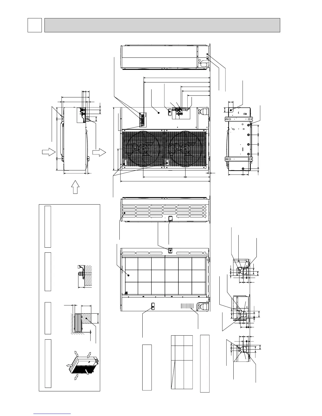
Rear piping cover
Front piping cover
Side Air Intake
Handle for moving
Piping Knockout Hole Details
637323
5527
92
65
4045
Power supply wiring hole
(2-:27Knockout)
Rear trunking hole
(Knockout)
Rear piping hole
(Knockout)
:92
922723
6373
4075
92
5519
Power supply wiring hole
(2-:27Knockout)
Right trunking hole
(Knockout)
Right piping hole
(Knockout)
:92
637323
5527
40 45
65
92
Power supply wiring hole
(2-:27Knockout)
Front trunking hole
(Knockout)
Front piping hole
(Knockout)
:92
Over
Over
Over
Over
Less than
Piping and wiring connections
can be made from 4 directions:
front, right, rear and below.
4 PIPING-WIRING DIRECTIONS
3 FOUNDATION BOLTS2 SERVICE SPACE
1 FREE SPACE (Around the unit)
Please secure the unit firmly
with 4 foundation (M10) bolts.
(Bolts and washers must be
purchased locally.)
<Foundation bolt height>
Dimensions of space needed
for service access are
shown in the below diagram.
The diagram below shows a basic
example.
Explanation of particular details are
given in the installation manuals etc.
30
FOUNDATION
10
500
500
150
Service space
FREE
Over 10mm
Over 10mm
Over 150mm
Over 1000mm
53
40
56
0
70
175600175
33030
37028 19
417
60 37
2-12%36 oval holes
(Foundation Bolt M10)
2-U Shaped notched holes
(foundation Bolt M10)
Side Air Intake
Rear Air Intake
Air Discharge
Installation Feet
999
995
*1 A
*2 339
950
322
23
371 635
1350
*1 439
Handle for moving
Handle for moving
Terminal Connections
Left···Power supply wiring
Right···Indoor/Outdoor wiring
Service Panel
(
Earth terminal
Brazing
)
PUHZ-P250YHA
PUHZ-P250YHA3
PUHZ-P200YHA
PUHZ-P200YHA3
:9.52
(3/8 inch)
:12.7
(1/2 inch)
421
A
447
· · · ·Refrigerant GAS pipe connection (FLARE):19.05 (3/4 inch)
· · · ·Refrigerant LIQUID pipe connection (FLARE)
*1· · · ·Indication of STOP VALVE connection location
*2· · · ·Refrigerant GAS PIPE connection(BRAZING) O.D:25.4
Example of Notes
14514514522030
81 219
71
71
Drain hole
(5-:33)
Bottom piping hole
(Knockout)
Side Air Intake
Air Intake
Rear Air Intake
Handle for moving
Handle for moving

 Loading...


