15
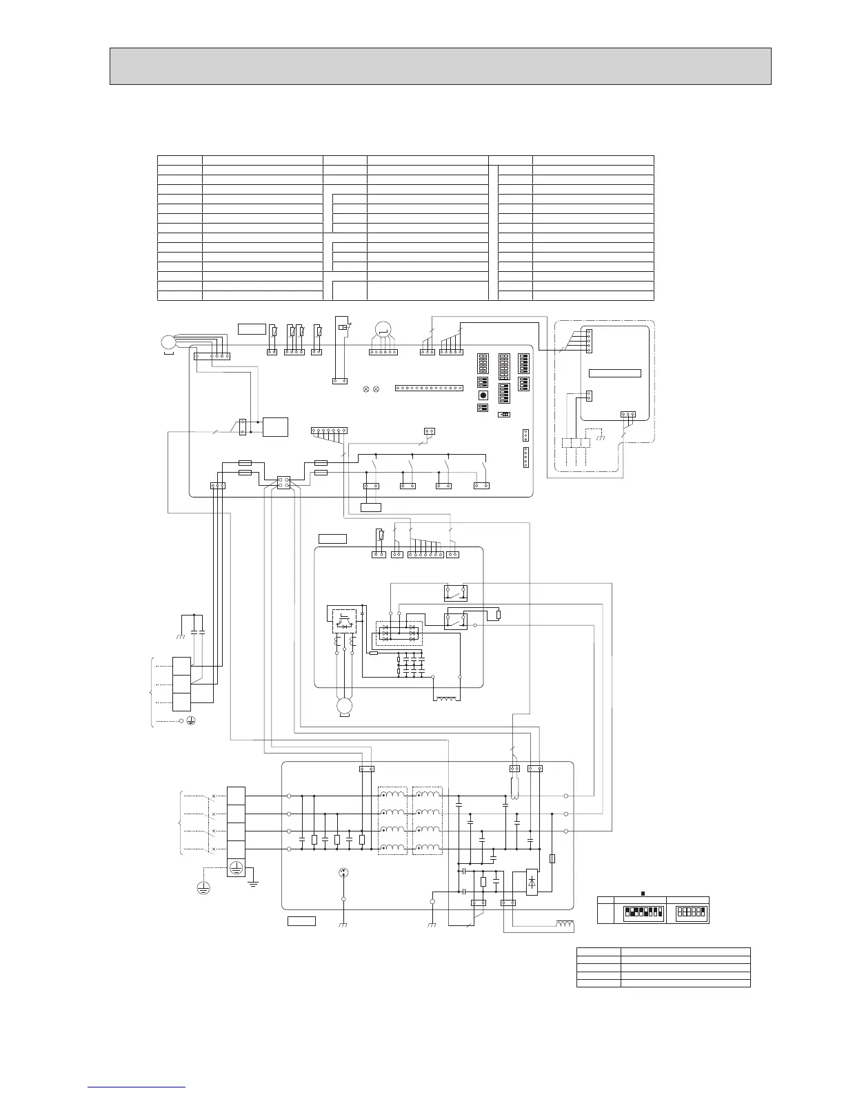
PUHZ-SP100YHA.UK
The black square ( ) indicates a switch position.
SYMBOL NAME SYMBOL NAME SYMBOL NAME
TB1 Terminal Block <Power Supply> RS Rush Current Protect Resistor SW4 Switch <Test Operation>
TB2 Terminal Block <Indoor/Outdoor> CY1, CY2 Capacitor SW5 Switch <Function Switch, Model Select>
MC Motor for Compressor P.B. Power Circuit Board SW6 Switch <Model Select>
MF1 Fan Motor TB-U/V/W
Connection Terminal
<U/V/W-Phase> SW7 Switch <Function Switch>
21S4 Solenoid Valve (Four-Way Valve)
TB-L1/L2/L3 Connection Terminal <L1/L2/L3-Power Supply>
SW8 Switch <Function Switch>
63H High Pressure Switch TB-P1/P3
Connection Terminal
SW9 Switch <Function Switch>
TH3 Thermistor <Liquid>
X52CA/B
52C Relay SWP Switch <Pump Down>
TH6 Thermistor <2-Phase Pipe> N.F. Noise Filter Circuit Board CN31 Connector <Emergency Operation>
TH7 Thermistor <Ambient>
LI1/LI2/LI3/NI
Connection Terminal <L1/L2/L3/N-Power Supply>
SS Connector <Connection for Option>
TH8 Thermistor <Heat Sink>
LO1/LO2/LO3
Connection Terminal <L1/L2/L3-Power Supply>
CNDM Connector <Connection for Option>
TH32 Thermistor <Comp. Surface> GD1, GD2
Connection Terminal
<Ground> CNM Connector <Connection for Option>
LEV-A Linear Expansion Valve C.B. Controller Circuit Board
LED1, LED2
LED <Operation Inspection Indicators>
DCL Reactor
SW1
Switch <Manual Defrost, Defect History,
Record Reset, Refrigerant Address>
F1, F2, F3, F4
Fuse <T6.3AL250V>
ACL4 Reactor
X51, X52, X54, X55
Relay
TB7 Terminal Block <M-NET connection>
SYMBOL NAME
CN5 Connector <Transmission>
CND Connector <Power Supply>
CN2M Connector <M-NET communication>
M-NET ADAPTER
TH8
t°
LEV-A
(WHT)
61
3
CNVMNT
(WHT)
CN4
(WHT)
CNMNT
(WHT)
31
5
1
CN5
(WHT)
3 1
TB7
5
1
2
5
1
CND
(WHT)
CN2M
(WHT)
M-NET
When M-NET adapter is connected
1
2
3
4
CNS
(WHT)
13
21S4
(GRN)
MF1
TRANS
CNF1
(WHT)
1
3
CNDC
(PNK)
CN2
(WHT)
CNAC
(WHT)
13
SV2
(BLU)
X55
X51
X52
13
SS
(WHT)
ACL4
BLK
BLK
WHT
WHT
WHT
RED
BLK
BLU
GRN/YLW
WHT
RED
CNAC1
(WHT)
CNCT
(RED)
CNAC2
(RED)
CNL
(BLU)
CNDC
(PNK)
P.B.
C.B.
N.F.
LO1
GD2
LO2
LO3
LI1
LI2
LI3
NI
TB1
TB2
POWER
SUPPLY
3N~
400V 50Hz
INDOOR
UNIT
1
F2
F1
F3
F4
TH7/6
(RED)
63H
(YLW)
TH3
(WHT)
TH7 TH6 TH3
41 21
3
1
t° t° t°
TH32
(BLK)
TH32
21
t°
63H
2
2
1
7
2
3
72 2
7
1
71
3121
LEV-A
M
LED1
LED2
CNM
(WHT)
1
14
3
1
5
1
3
5
CNDM
(WHT)
CN51
(WHT)
SW7
SW6SW1
SW9
CN31
*
1
*
1
SW5SW8SW4 SWP
21S4
A B S
+
+
1331
31
L1
L2
L3
N
S1
S2
S3
YLW
CY2
CY1
ORN
BLK
BRN
MS
3~
2
2
M-NET ADAPTER
BLK
GD1
13
SV1
/CH
(GRY)
X54
1 2 3 4 5 6 7 8
OFF
ON
100Y
MODEL
SW6
*
1 MODEL SELECT
*
2 SW5 -1 to 5 : Function Switch
SW5-6 *2
OFF
ON
1 2 3 4 5 6
RS
CN6
(WHT)
CN5
(RED)
CN2
(WHT)
CN4
(WHT)
TB-U
TB-V
TB-W
U
W
V
DCL
RED
WHT
BLK
MC
WHT
RED
BLK
RED
RED
X52CA
BLK
-
MS
3~
71 2122 11
TB-P3
TB-P1
TB-L3
TB-L2
L3IN
TB-L1
+
-
+-
+ + +
+ + +
X52CB
L3OUT

 Loading...


