16
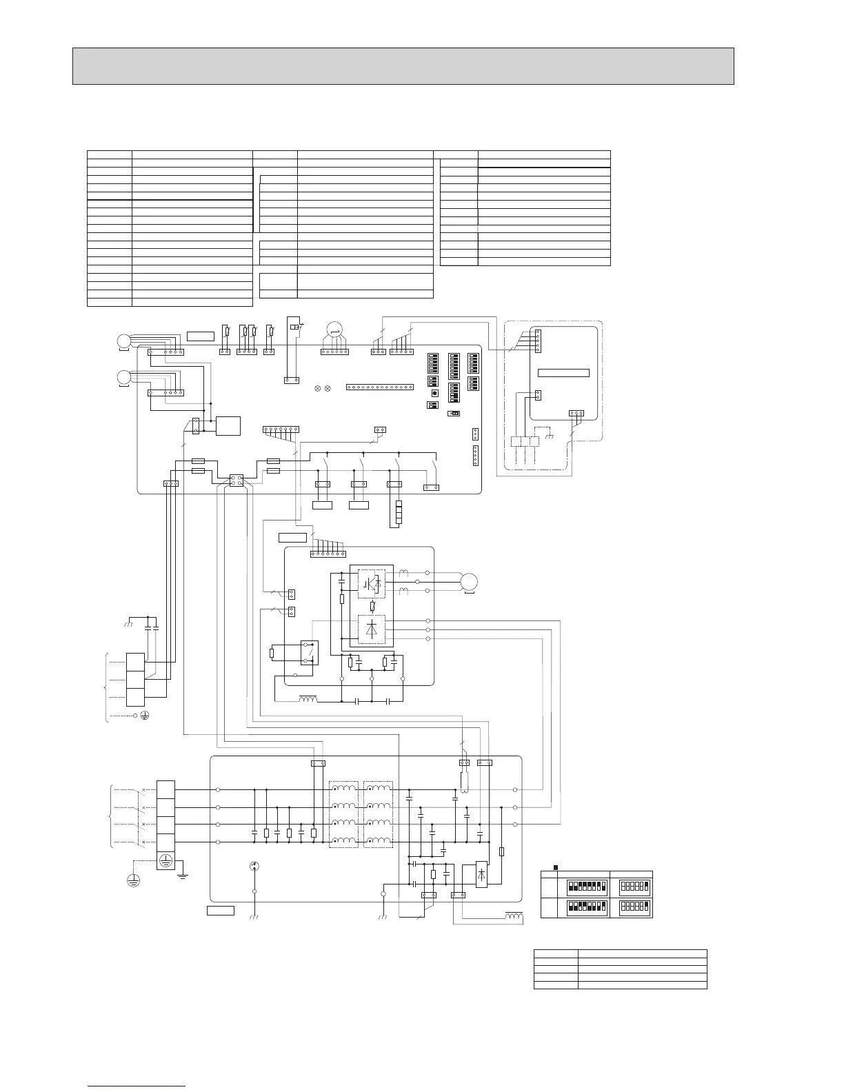
PUHZ-SP125YHA.UK PUHZ-SP140YHA.UK
TB1
MC
MF1, MF2
21S4
TH3
TH6
TH7
LEV-A
ACL4
Terminal Block<Power Supply >
TB2 Terminal Block<Indoor/Outdoor >
Motor for Compressor
Fan Motor
Solenoid Valve (Four-Way Valve)
63H High Pressure Switch
CH
Crankcase Heater
SV
Solenoid Valve (Bypass Valve)
Thermistor<Liquid>
Thermistor<2-Phase Pipe>
Thermistor<Ambient>
TH8 Thermistor (internal) <Heat Sink>
TH32 Thermistor<Comp. Surface>
Electronic Expansion Valve
Reactor
DCL Reactor
RS
Rush Current Protect Resistor
CY1,CY2
Capacitor
CB1, CB2
Main Smoothing Capacitor
Power Circuit Board
Connection Terminal<U/V/W-Phase>
P.B.
TB-U/V/W
Noise Filter Circuit Board
Connection Terminal
<L1/L2/L3/N-Power Supply
>
N.F.
LI1/LI2/LI3/NI
Connection Terminal
<L1/L2/L3/N-Power Supply
>
LO1/LO2/LO3
Controller Circuit Board
SW8
Connector<Emergency Operation>
CN31
C.B.
Connection Terminal<Ground>GD1, GD2
SYMBOL NAME SYMBOL NAME SYMBOL NAME
Connection Terminal
TB-P1
Connection Terminal
<L1/L2/L3-Power Supply
>
TB-L1/L2/L3
Switch<Function Switch>
SW9
Switch<Pump Down>
SWP
Switch<Manual Defrost, Defect History, Record
Reset, Refrigerant Address>
Switch<Function Switch, Model Select>
Switch<Function Switch>
Switch<Function Switch>
SW1
SW5
Switch<Model Select>
SW6
SW7
Switch<Test Operation>
SW4
LED1,LED2
LED<Operatiion Inspection Indicators>
CNM
Connector<Connection for Option>
SS
Connector<Connection for Option>
CNDM
Connector<Connection for Option>
FUSE<T6.3AL250V>
F1,F2,F3,F4
Connection Terminal
TB-P2
Connection Terminal
TB-C1
Connection Terminal
TB-N1
52C Relay
X52A
X51,X52,X54,X55
Relay
TB7 Terminal Block <M-NET connection>
SYMBOL NAME
CN5 Connector <Transmission>
CND Connector <Power Supply>
CN2M Connector <M-NET communication>
M-NET ADAPTER
1 2 3 4 5 6 7 8
1 2 3 4 5 6 7 8
MODEL
SW6
*1 MODEL SELECT
*2 SW5 -1 to 5 : Function Switch
SW5-6 *2
OFF
ON
125Y
OFF
ON
OFF
1 2 3 4 5 6
1 2 3 4 5 6
OFF
ON
140Y
ON
is the switch position
LEV-A
(WHT)
61
3
CNVMNT
(WHT)
CN4
(WHT)
CNMNT
(WHT)
31
5
1
71
2
1
2
1
1
2
3
4
CNS
(WHT)
13
21S4
(GRN)
MF1
TRANS
CNF1
(WHT)
CNF2
(WHT)
1
3
CNDC
(PNK)
CN2
(WHT)
CNAC
(WHT)
13
SV2
(BLU)
X55
X51
X52
13
SS
(WHT)
+
--
--
+
+ +
+
+
ACL4
DCL
X52A
TB-P1
CN2
(WHT)
TB-P2
CB1 CB2
TB-C1 TB-N1
TB-W
BLK
WHT
RED
RED
BLK
WHT
RED
BLK
BLK
BLK
WHT
WHT
WHT
RED
BLK
BLU
GRN/YLW
WHT
RED
TB-V
TB-U
TB-L3
TB-L2
TB-L1
W
V
U
MC
CN4
(WHT)
CNAC1
(WHT)
CN5
(RED)
CNCT
(RED)
CNAC2
(RED)
CNL
(BLU)
CNDC
(PNK)
RS
P.B.
C.B.
N.F.
LO1
GD1
GD2
LO2
LO3
LI1
LI2
LI3
NI
TB1
TB2
POWER
SUPPLY
3N~
400V 50Hz
INDOOR
UNIT
1
F2
F1
F3
F4
TH7/6
(RED)
63H
(YLW)
TH3
(WHT)
TH7 TH6 TH3
41 21
3
1
t° t° t°
TH32
(BLK)
TH32
21
t°
63H
2
2
1
7
2
7
RED
WHT
BLK
7
1
71
BLK
BLK
3121
LEV-A
M
LED1
LED2
CNM
(WHT)
1
14
3
1
5
1
3
5
CNDM
(WHT)
CN51
(WHT)
SW7
SW6SW1
SW9
CN31
*1*1
SW5SW8SW4 SWP
SV21S4
MS
3~
+
1331
31
L1
L2
L3
N
S1
S2
S3
YLW
CY2
CY1
ORN
BRN
MS
3~
2
2
2
2
13
SV1
/CH
(GRY)
X54
CH
CN5
(WHT)
3 1
TB7
5
1
2
5
1
CND
(WHT)
CN2M
(WHT)
M-NET
When M-NET adapter is connected
3
A B S
M-NET ADAPTER
t°
TH8
MF2
7
1
MS
3~
+
--

 Loading...


