3 - 14 3 - 14
3 SPECIFICATIONS
MELSEC-Q
[SFC system processing time calculation example]
Using the Q25HCPU as an example, the processing time for the SFC system is calculated
as shown below, given the following conditions.
• Designated at initial START
• Number of active blocks: 30 (active blocks at SFC program)
• Number of inactive blocks: 70 (inactive blocks at SFC program)
• Number of nonexistent blocks: 50 (number of blocks between 0 and the max. created
block No. which have no SFC program)
• Number of active steps: 60 (active steps within active blocks)
• Active step transition conditions: 60
• Steps with satisfied transition conditions: 10
(active steps (no HOLD steps) with satisfied transition conditions)
SFC system process time =(14.5 × 30) + (5.2 × 70) + (1.8 × 50)
+ (10.6 × 60) + (4.3 × 60) + (56.2 × 10) + 46.6
= 2391.6 µs
2.40 ms
In this case, calculation using the equation shown above results in an SFC system
processing time of 2.40 ms.
The scan time is the total of the following times;
SFC system processing time, main sequence program processing time, SFC active step
transition condition time, and CPU END processing time.
The scan time is the total of the following times:
SFC system processing time, main sequence program processing time, processing time of
ladder circuit having transition conditions associated with SFC's active steps, and CPU
module's END processing time.
The number of active steps, the number of transition conditions, and the number of steps
with satisfied transition conditions varies according to the conditions shown below.
• When transition condition is unsatisfied
• When transition condition is satisfied (without continuous transition)
• When transition condition is satisfied (with continuous transition)
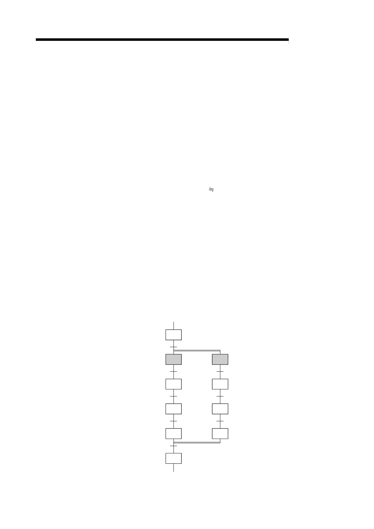
The method for determining the number of the above items is illustrated in the SFC diagram below.
Step 1
Step 2
Step 3
Transition
condition 1
Transition
condition 2
Step 4
Transition
condition 3
Step 5
Transition
condition 4
Step 10
Transition
condition 8
Step 6
Step 7
Transition
condition 5
Step 8
Transition
condition 6
Step 9
Transition
condition 7

 Loading...


