4 - 35 4 - 35
4 SFC PROGRAM CONFIGURATION
MELSEC-Q
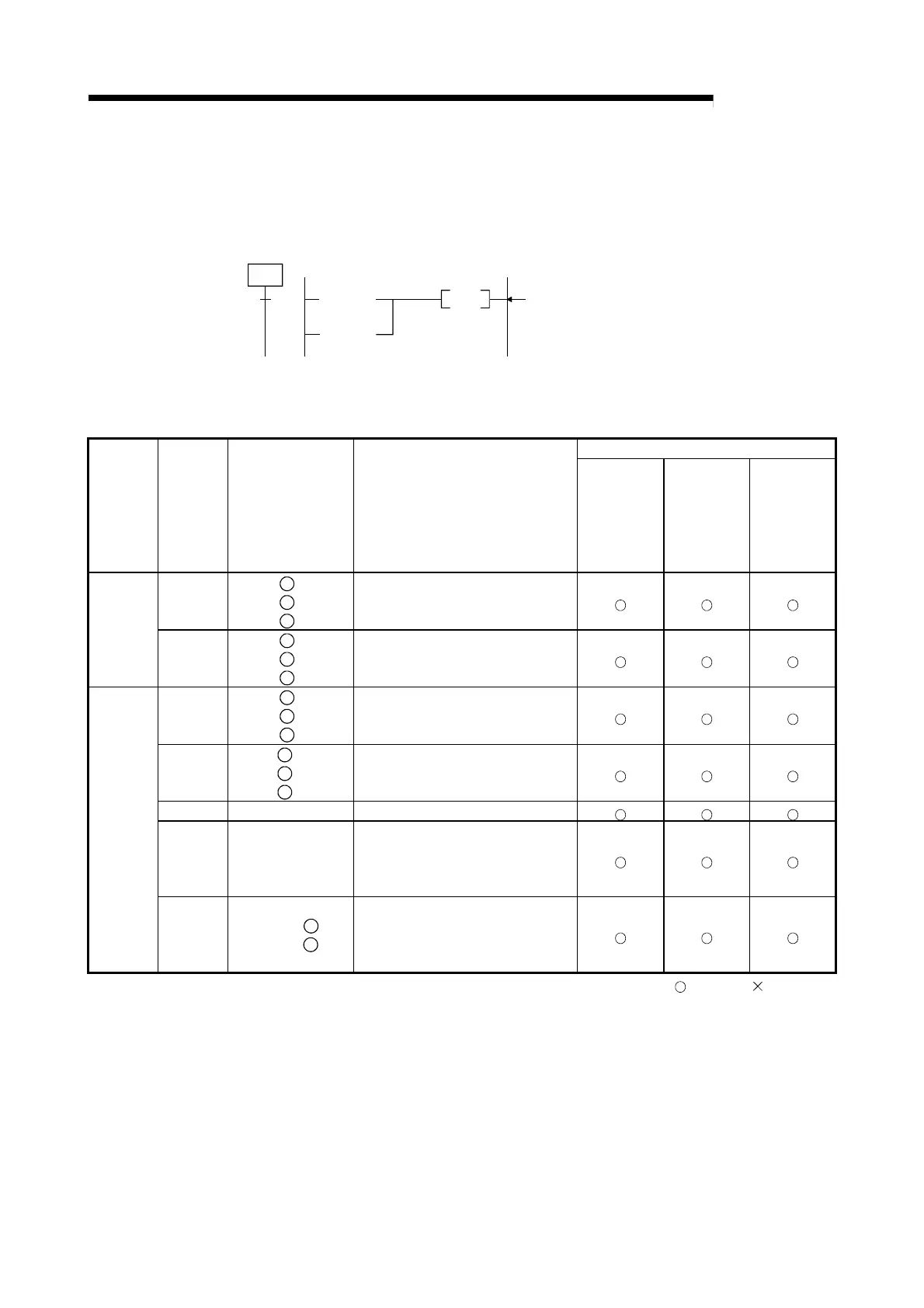
(4) Transition condition program
(a) Transition condition program expression
Transition condition programs can be used only for contact or contact-equivalent
instructions.
The transition condition program is expressed as the following ladder circuit:
Condition
TRAN
[TRAN] is a dummy outpu
Condition
(b) Instructions used
Instructions which can be used in a transition condition program are listed below.
CPU Module Type
Class
Instruction
Code
Instruction expression Function
Basic model
QCPU
High
Performance
Model QCPU,
Process CPU,
Redundant
CPU
Universal
model QCPU
LD
AND
OR
a
S
& a
S
| a
S
Operation START (N/O contact)
Serial connection (N/O contact)
Parallel connection (N/O contact)
Contacts
LDI
ANI
ORI
b
S
& b
S
| b
S
Operation START (N/C contact)
Serial connection (N/C contact)
Parallel connection (N/C contact)
LDP
ANDP
ORP
p
S
& p
S
| p
S
Leading edge pulse operation START
Leading edge pulse serial connection
Leading edge pulse parallel connection
LDF
ANDF
ORF
f
S
& f
S
| f
S
Trailing edge pulse operation START
Trailing edge pulse serial connection
Trailing edge pulse parallel connection
INV & INV Operation result inversion
MEP
MEF
& MEP
& MEF
Operation results converted to leading
edge pulse (step memory)
Operation results converted to trailing
edge pulse (step memory)
Contacts
EGP
EGF
& EGP
D
& EGF
D
Operation results converted to leading
edge pulse (memory)
Operation results converted to trailing
edge pulse (memory)
: Usable, : Unusable

 Loading...


