6
FUNCTIONS
6.11 Monitor Function
6.11.3 Enforced ON/OFF of external I/O
6
- 54
1
Overview
2
Performance
Specification
3
Sequence Program
Configuration and
Execution Conditions
4
I/O Nunber Assignment
5
Memories and Files
Handled by CPU Module
6
Functions
7
Communication with
Intelligent Function
Module
8
Parameters
(1) Operation performed at enforced ON/OFF
It is possible to perform enforced ON (Set forced ON) enforced OFF (Set forced OFF)
and cancel enforced ON/OFF (Cancel it) with the enforced ON/OFF
function.
Note6.12
Note12
The operations for performing enforced ON, enforced OFF and canceling enforced
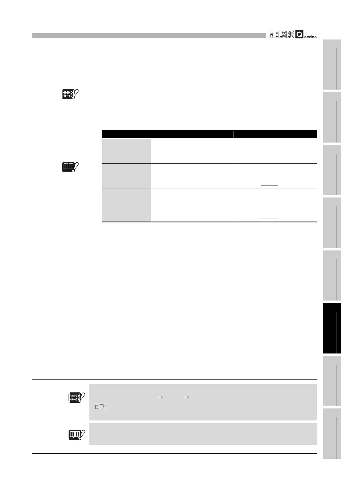
ON/OFF are shown in Table6.17.
Note13
Note12
Table6.17 Operation performed at enforced ON/OFF cancellation
Operation Input (X) operation Output (Y) operation
During canceling
(no operations)
Performs sequence program
operations with external input.
Outputs the results of sequence
program operations
externally.
Note6.13
During enforced
ON
Performs sequence program
operations in the enforced ON
status.
Outputs "ON" externally regardless
of the results of sequence program
operations.
Note6.13
During enforced
OFF
Performs sequence program
operations in the enforced OFF
status.
Outputs "OFF" externally
regardless of the results of
sequence program
operations.
Note6.13
Note13
Basic
Note6.12
The enforced ON registration and enforced OFF registration cannot be executed for Basic model
QCPU by selecting [Online] [Debug] [Forced input output registration/cancellation]
(
(3) in this section).
This operation can be executed for Basic model QCPU by
conducting device test with GX Developer.
Basic
Note6.12
Note6.13
Redundant
In the backup mode, the enforced ON/OFF cannot be executed for the output (Y) of the standby
system.
Note6.13
Redundant
 Loading...

