3 - 23 3 - 23
MELSEC-Q
3 SPECIFICATIONS
3.4.9 Write data error codes (buffer memory address 19: Un\G19)
(1) The error codes generated by the A/D converter modules are stored here.
(2) See Section 8.1 for the details of the error codes.
3.4.10 Setting ranges (buffer memory addresses 20, 21: Un\G20, Un\G21)
(1) These areas are used to confirm the setting ranges of the A/D converter module.
(2) The setting values for CH1 to CH4 are stored in buffer memory address 20
(Un\G20) and setting values for CH5 to CH8 are stored in buffer memory address
21 (Un\G21). In the case of the Q64AD module, buffer memory address 21
(Un\G21) is invalid.
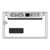
b15 to b12
CH4
Un\G20
CH8
Un\G21
b11 to b8
CH3
CH7
b7 to b4
CH2
CH6
b3 to b0
CH1
CH5
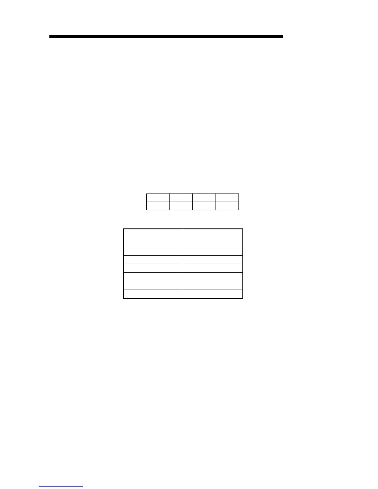
The setting values are as follows.
Input range Setting value
4 to 20 (mA) 0
H
0 to 20 (mA) 1
H
1 to 5 (V) 2
H
0 to 5 (V) 3
H
–10 to 10 (V) 4
H
0 to 10 (V) 5
H
User range setting F
H
(3) Default setting is 0.
When the setting for Q68ADV is 0, the analog input range operates between 0 to
10V.
(When the setting is 5
H
, the analog input range will be the same as above.)
 Loading...