-
91
-
'16 • SCM-T-199
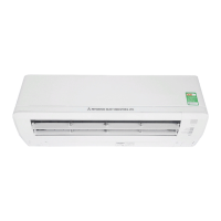
10.HOWTOOPEN,CLOSE,REMOVEANDINSTALL
THE AIR INLET PANEL
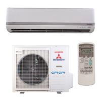
11. HOW TO REMOVE AND INSTALL THE BOTTOM AND
FRONT PANEL
1. Open
Pull the air inlet panel at both ends of lower part
and release latches, then pull up the panel until
you feel resistance.
(The panel stops at approx. 70° open position)
2.Close
Hold the panel at both ends of lower part, lower
it downward slowly, then push it slightly until the
latch works.
3. Removing
Open the panel by 90 degrees (as shown in the
right illustration) and then pull it forward.
4. Installing
Insert the panel arm into the slot on the front
panel from the position shown in right illustra-
tion, hold the panel at both ends of lower part,
lower it downward slowly, then push it slightly
until the latch works.
Approx. 90°
1. Bottom panel
1.1. Removing
(1) Remove the 2 screws (in the cap).
(2) Remove the 2 hooks of left and right side and
then bottom panel can be removed.
1.2.Installing
(1) Install the 2 hooks of left and right side.
(2) Secure the bottom panel with the 2 screws
(in the cap).
2.Frontpanel
2.1.Removing
(1)Removetheairinletpanel,theairltersandthe
bottom panel.
(2) Remove the 2 screws.
(3) Remove the 4 upper latches and then front
panel can be removed.
2.2.Installing
(1)Covertheunitwiththefrontpanelandx4
upper latches.
(2) Secure the front panel with the 2 screws.
(3) Install the bottom panel, the air inlet panel and
theairlters.
Bottom panel
Screw (in the cap)
Screw
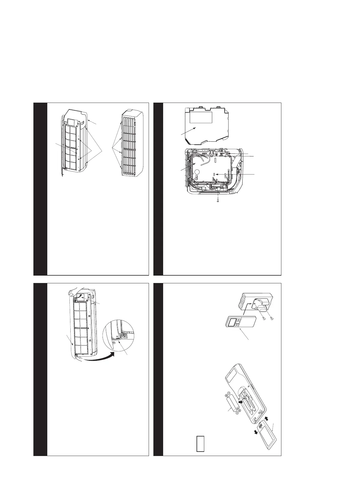
12.INSTALLINGWIRELESSREMOTECONTROL 13. TERMINAL CONNECTION FOR AN INTERFACE
Mount the batteries
(1) Slide and take out the cover of backside.
(2) Mount the batteries [R03 (AAA, Micro),
×2 pieces] in the body properly.
(Fithepoleswiththeindicationmarks+&−)
(3) Set the cover again.
NOTE
• Do not use new and old batteries together.
• In case the unit is not operated for a long time,
take out the batteries
Installing remote control holder
(1) Select the place where the unit can receive
signals.
(2) Fix the holder to pillar or wall with wood
screws.
To install wired remote control,
superlink etc., interface kit is
needed.
(1) Remove the air inlet panel,
bottom panel and front panel.
(2) Remove the control cover.
(Remove the screw.)
(3) There is a terminal
(respectively marked with CNS)
for the indoor control board.
While connecting an interface,
connect to the respective
terminal securely with the
connection harness supplied
with an optional “Interface
connection kit SC-BIKN-E” and
fasten the connection harness
onto the indoor control box with
the clamp and screw supplied
with the kit.
For more details, refer to the
user’s manual of “Interface
connection kit SC-BIKN-E”.
w
Screw
Clamp
Indoor unit PCB Control cover
Cover
Wood screws
ø3.5 X 16
Wireless
remote control
Battery
 Loading...