-
98
-
'16 • SCM-T-199
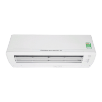
9. CONNECTING PIPING WORK
1. Preparation of connecting pipe
1.1. Selecting connecting pipe
Select connecting pipe according to the following table.
Gas pipe ø9.52
Liquid pipe ø6.35
• Pipe wall thickness must be greater than or equal to 0.8 mm.
• Pipe material must be O-type (Phosphorus deoxidized seamless copper pipe ICS 23.040.15, ICS
77.150.30).
1.2.Cuttingconnectingpipe
(1) Cut the connecting pipe to the required length with pipe cutter.
(2)
Hold the pipe downward and remove the burrs. Make sure that no foreign material enters the pipe.
(3) Cover the connecting pipe ends with the tape.
2.Pipingwork
2.1.Flaringpipe
(1)
Takeoutarenutsfromtheservicevalvesofindoorunitandengagethemontoconnectingpipes.
(2) Flarethepipesaccordingtotableandgureshownbelow.
Flare dimensions for R410A are different from those for conventional refrigerant.
AlthoughitisrecommendedtousethearingtoolsdesignedspecicallyforR410A,conventionalar-
ingtoolscanalsobeusedbyadjustingthemeasurementofprotrusionBwithaareadjustmentgauge.
Copperpipe
outer diameter
A
0
–0.4
Copperpipe
outer diameter
Rigid (clutch) type
R410A Conventional
ø6.35 9.1 ø6.35
0-0.5 1.0-1.5
ø9.52 13.2 ø9.52
2.2Connectingpipes
(1) Connect pipes on both liquid and gas sides.
(2)Tightennutstospeciedtorqueshowninthetablebelow.
Gas side
Service valve size (mm) Tightening torque (N·m)
ø6.35 (1/4") 14-18
ø9.52 (3/8") 34-42
CAUTION
•
Donotapplyrefrigeratingmachineoiltothearedsurface.Itcancauserefrigerantleakage.
• Donotapplyexcesstorquetothearednuts.Thearednutsmaycrackresultinginrefrigerant
leakage.
3. Heating and condensation prevention
(1) Dress the connecting pipes (both liquid and gas pipes) with insulation to prevent it from heating and
dew condensation.
Use the heat insulating material which can withstand 120°C or higher temperature. Make sure that insu-
lation is wrapped tightly around the pipes and no gap is left between them.
(2) Wrap the refrigerant pipings of indoor unit with indoor unit heat insulation using tape.
(3) Covertheare-connectedjoints(indoorside)withtheindoorunitheatinsulationandwrapitwithanin-
sulation pad (standard accessory provided with indoor unit).
(4) Wrap the connecting pipes, connecting cable and drain hose with the tape.
(2) (3) (4)
Insulation pad
Position it so that the slit area faces upward.
Connecting cable
Liquid pipe
Drain hose
Gas pipe
Insulation
Tape
NOTE
Locations where relative humidity exceeds 70%, both liquid and gas pipes need to be dressed with 20mm
or
thicker heat insulation materials.
CAUTION
• Improper insulation can cause condensate(water) formation during cooling operation.
Condensate can leak or drip causing damage to household property.
• Poor heat insulating capacity can cause pipe outer surface to reach high temperature during heating
operation. It can cause cable deterioration and personal injury.
4. Finishing work
Pipe
assembly
Screw
(1) Make sure that the exterior portion of connecting pipes, connecting cable
and drain hose is wrapped properly with tape. Shape the connecting pipes
to match with the contours of the pipe assembly route.
(2) Fix the pipe assembly with the wall using clamps and screws. Pipe assem-
bly should be anchored every 1.5m or less to isolate the vibration.
(3) Install the service cover securely. Water may enter the unit if service cover
is not installed properly, resulting in unit malfunction and failure.
CAUTION
Make sure that the connecting pipes do not touch the components within the unit. If pipes touch the
internal components, it may generate abnormal sounds and/or vibrations.
 Loading...