5. Adjustment of test operation
5.1 Pre-operation inspection
(1) Check the seal going through the board of
refrigeration unit.
(2) Check if the clamp of the tubing is adequate.
(3) Check if the drain hose is connected properly and
the clamp is proper.
(4) Check the belt for looseness, degree of parallel
(Coming out of the interline) and flaw.
(5) Check if components such as compressor, pully,
belt, tubing and wiring are touching each other.
(6) More tightening of fixing bolts for the following
units.
•
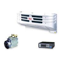
Refrigeration unit
•
Compressor and bracket
•
Magnet clutch
•
Tension pulley and bracket
•
Fan motor and fan
(7) Check the electric wiring for mis-wiring and the
clamp for properness.
(8) Check the wiring terminal for looseness and the
covering of wiring for flaw.
(9) Check the refrigerant system for gas leakage (oil
leakage).
(10) Check electric wiring for grounding and defective
insulation. (Type 2 only)
5.2 Inspection during operation
(1) Check the compressor, magnet clutch, motor, fan
and tubing for abnormal sound and vibration.
(2) Check the refrigerant sight glass for color and
degree of flashing.
(3) Check the compressor and magnet clutch for start
and stop due to the thermostat.
(4) Check refrigeration (indication by temperature
display and high and low pressure).
(5) Check the defroster for operation.
(6) Check the dual pressure switch for operation.
(7) Check the motor for drive (Type 2 only) and
buzzer with ignition switch "ON".
6. Daily operation
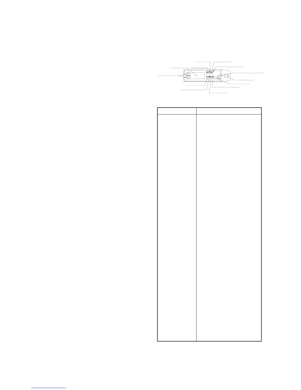
6.1 Description of operation for the controller
Description of operation for the controller
Name Operation
The switch starts or stops the
refrigeration unit.
The lamp (green) is lit when the
operation switch is on.
The switch turns on the forcible
defrosting operation.
The lamp (orange) is lit when
defrosting is in operation.
When the alarm lamp lights or blinks,
press the switch, and all faults which
occur will be indicated as the code on
the digital display unit.
When a fault occurs, the alarm lamp
(red) lights and blinks.
The in-container temperature,
incontainer preset temperature, fault
display code and integrated operation
time are displayed according to the
switches.
The switch changes the incontainer
preset temperature.
The switch makes the working time
(operation hours) of the evaporator
fan displayed.
Press the hours switch, and the lamp
(green) will come on.
When the refrigeration unit stops,
press this switch, and the incontainer
temperature will be displayed on the
digital display unit for 5 seconds.
Moreover, when the refrigeration unit
runs, press this switch, and the
incontainer temperature will be
displayed if the preset temperature,
fault code or integrated operation
time is displayed in the display unit.
Press the display switch, and the
lamp (green) will come on.
Buzzer prevents improper start.
Keeping the power code for motor
drive connected, turn the vehicle
ignition key to "ON", and the buzzer
integrated in the controller will sound
to stop the refrigeration unit.(Even if
the refrigeration unit stops, the buzzer
will sound.
– 6 –
 Loading...