Do you have a question about the Mitsubishi TDJ430D and is the answer not in the manual?
Explains the coding system used for unit model identification.
Lists critical safety warnings and precautions for operation and maintenance.
Details important cautions to prevent minor injuries or equipment damage.
Describes the microcomputerized controller's display and diagnostic functions.
Explains the engine drive and motor drive (Type 2) systems.
Details how the refrigeration unit's cooling operation is controlled by temperature.
Explains the automatic and manual defrosting operations to maintain efficiency.
Describes safety devices that protect the unit from high pressure or temperature.
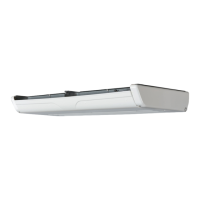
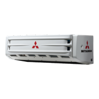
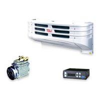
Identifies the main refrigeration unit assembly.
Shows the components of the control panel and display.
Illustrates the compressors for TDJ300D and TDJ430D models.
Identifies the motor pack and power source box for Type 2 units.
Lists checks to perform before unit operation for safety and proper function.
Details checks required while the unit is running to ensure correct operation.
Explains the function of each switch and indicator on the controller.
Covers changing preset temperature, displaying operation time, and fault history.
Describes how to clear operation time and change defrost timer settings.
Outlines the sequence for cooling operation for engine and motor drive types.
Explains how to view different information on the digital display.
Details automatic and manual defrosting operations to prevent ice buildup.
Steps to inspect the storage and unit before loading goods.
Instructions for loading goods to ensure proper air circulation and temperature.
Steps for safe and efficient unloading of goods.
Advises on long-term usage, maintenance during non-use, and operational practices.
Illustrates the layout of refrigerant pipes for engine and motor drive types.
Diagrams showing the refrigerant flow during freezing and defrosting operations.
Describes the construction and lubrication system of the compressors.
Explains the role of the magnet clutch in compressor operation.
Details the function of the heat accumulator in the refrigerant cycle.
Explains the accumulator's role in separating refrigerant for Type 2 systems.
Describes the defrost and liquid injection electromagnetic valves.
Explains the purpose of the check valve in preventing backflow.
Describes the receiver's function and safety features.
Guides on checking refrigerant level and water content via the sight glass.
Explains the dryer's function in removing moisture and foreign materials.
Provides specifications and notes for the condenser fan motor.
Details specifications for the evaporator fan motor.
Outlines the benefits and functions of the multi-function valve.
Explains how to adjust the expansion valve for optimal refrigerant flow.
Describes the DTS function in ending the defrost cycle.
Lists the CUT IN/OUT pressure settings for the DPS.
Explains how the TH sensor controls unit operation based on temperature.
Details the Td sensor's role in monitoring compressor delivery temperature.
Highlights the controller's advanced features like digital display and diagnostics.
Describes the optional drain hose heater and its activation.
Provides the sequence diagram for electrical connections.
Details the cooling operation sequence for engine-driven units.
Explains how thermostat cycles control cooling operation.
Outlines the steps involved in the defrost operation cycle.
Details the protection device operation specific to motor-driven units.
Comprehensive checks required upon unit installation and initial test run.
Routine checks to be performed daily for proper unit functioning.
Periodic checks to be done monthly for belt tension, cleaning, and refrigerant status.
Checks required every six months, including relay contacts and wiring.
Tables specifying torque values for flare nuts and general bolts.
Guidelines for users on daily checks, including gas leakage and coil cleaning.
Instructions for proper loading to ensure temperature circulation and prevent issues.
Important considerations for periodic inspections, including belt tension and parts replacement.
A form for recording inspection results for installation, test run, and periodic checks.
Tables showing pressure values for TDJ300D and TDJ430D under various conditions.
A table correlating defects with causes in the refrigerant system.
Uses pressure readings to diagnose common refrigeration system issues.
Identifies causes and remedies for insufficient refrigeration.
Lists potential causes for abnormal sounds and their solutions.
Step-by-step guide for charging refrigerant, including evacuation and gas charging.
Troubleshooting guide based on controller display indications and alarm lamps.
Flowchart for diagnosing controller-related defects based on display codes.
Troubleshooting for units not operating or having abnormal indications.
Steps to diagnose and resolve issues with defrost operation.
Troubleshooting specific to motor drive operation, including fan and compressor failures.
Safety guidelines for handling printed circuit boards to prevent damage.
Details the pin configurations for controller connectors.
Steps for inspecting the controller's electrical connections and voltage readings.
Explains how jumper cables configure model, refrigerant, heating, and fan settings.
Key precautions to ensure safe and proper unit installation, avoiding leaks and hazards.
Specific guidance on component alignment, hose routing, and piping installation.
Illustrates the overall layout and mounting positions of the refrigeration unit.
Procedures for preparing the vehicle before unit installation, including safety measures.
Safe practices for handling and mounting the refrigeration unit components.
Provides detailed dimensional drawings for the compressors.
Shows the overall dimensions and mounting points of the refrigeration unit.
Displays the physical dimensions of the controller unit.
Outlines the dimensions for the motor pack.
Shows the physical dimensions of the power source box.
Specifies drilling and mounting details for the unit on the van body.
Details for ensuring a proper seal and alignment of the unit with the van.
Guidelines for installing protection guards and bulkheads inside the van.
Specifies clearance requirements for the unit cover.
Shows the piping configuration for Type 1 units.
Illustrates the piping layout for Type 2 units with motor packs.
Provides specific piping diagrams and connection points for different types.
Instructions for installing an optional marker lamp on the refrigeration unit.
| Brand | Mitsubishi |
|---|---|
| Model | TDJ430D |
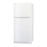
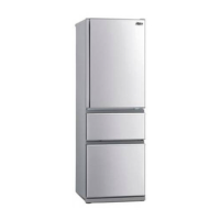
| Category | Refrigerator |
| Language | English |