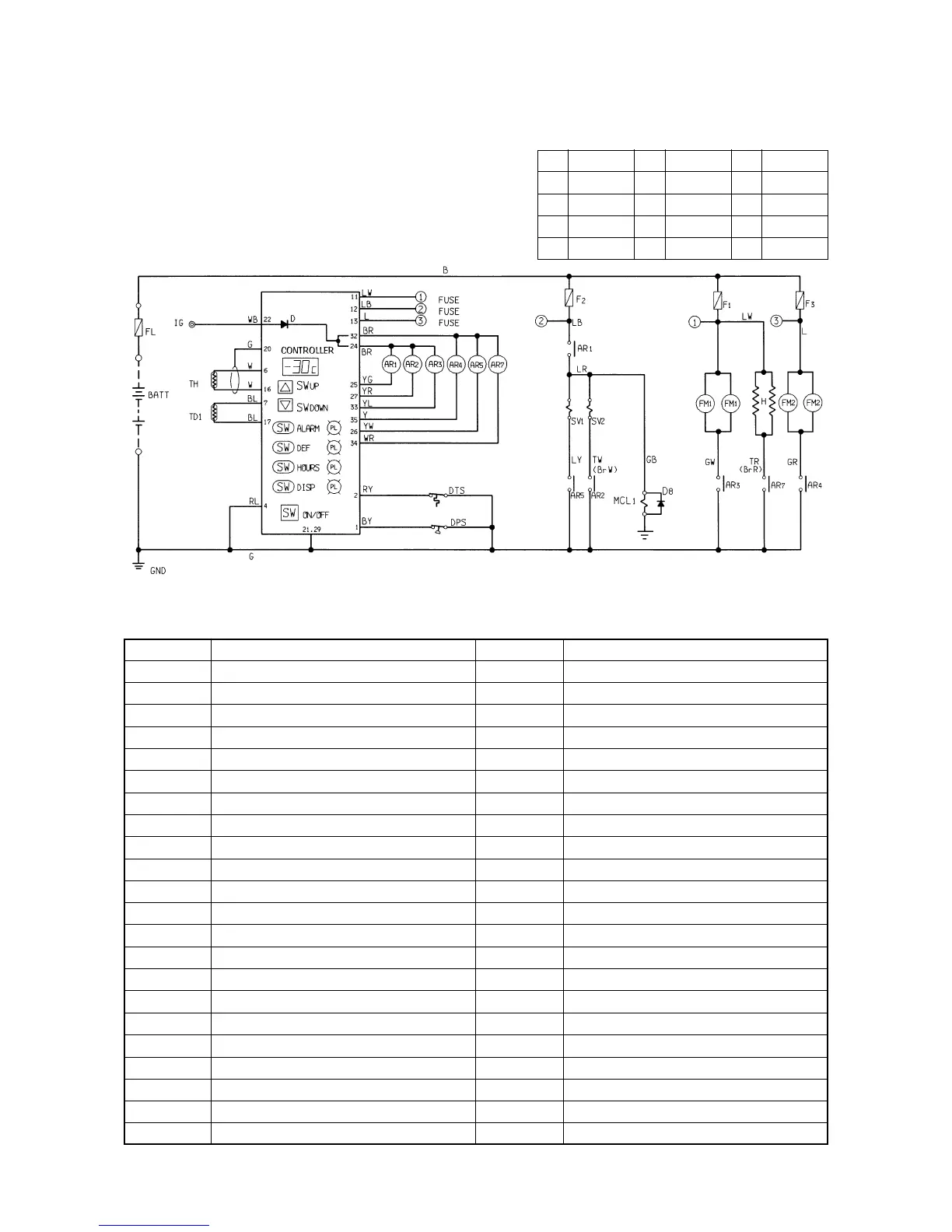
11. Electric wiring diagram
11.1 Sequence diagram
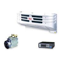
(1) TDJ300D-1L2, TDJ430D-1L2
Remarks: Three FM
1
(evaporator fan motor) are provided on TDJ430D.
– 21 –
Explanation of mark
SYMBOL
SW
UP
SW
DOWN
SW
ALARM
SW
DEF
SW
HOURS
SW
ON/OFF
SW
DISP
PL
ALARM
PL
DEF
PL
HOURS
PL
DISP
TH
DPS
TD
1
DTS
FL
BATT
IG
NAME
Temperature setting switch (up)
Temperature setting switch (down)
Alarm switch
Defrost switch
Hours switch
Operation switch
Display switch
Alarm lamp
Defrost indication lamp
Hours indication lamp
Display indication lamp
Storage temperature sensor
Dual pressure switch
Td sensor (engine side)
Defrost thermostat
Fusible link
Battery
Ignition terminal
SYMBOL
AR
1
AR
2
AR
3
AR
4
AR
5
AR
7
F
1
F
2
F
3
FM
1
FM
2
H
MCL
1
SV
1
SV
2
NAME
Thermostat relay
Liquid injection electromagnetic relay
Evaporator fan motor relay
Condenser fan motor relay
Defrost electromagnetic valve relay
Drain hose heater relay
Fuse (*1: 15A, *2: 25A)
Fuse (10A)
Fuse (15A)
Evaporator fan motor
Condenser fan motor
Drain hose heater (option)
Magnet clutch (engine side)
Defrost electromagnetic valve
Liquid injection electromagnetic valve
*1: TDJ300D
*2: TDJ430D
Code Wire color Code Wire color Code Wire color
B Black Y Yellow P Pink
W White L Blue V Violet
R Red Br Brown Gy Gray
G Green O Orange Lg Light green
Wire color codes
wire colors are identified by the following color codes.
 Loading...