22 23
TCHT011
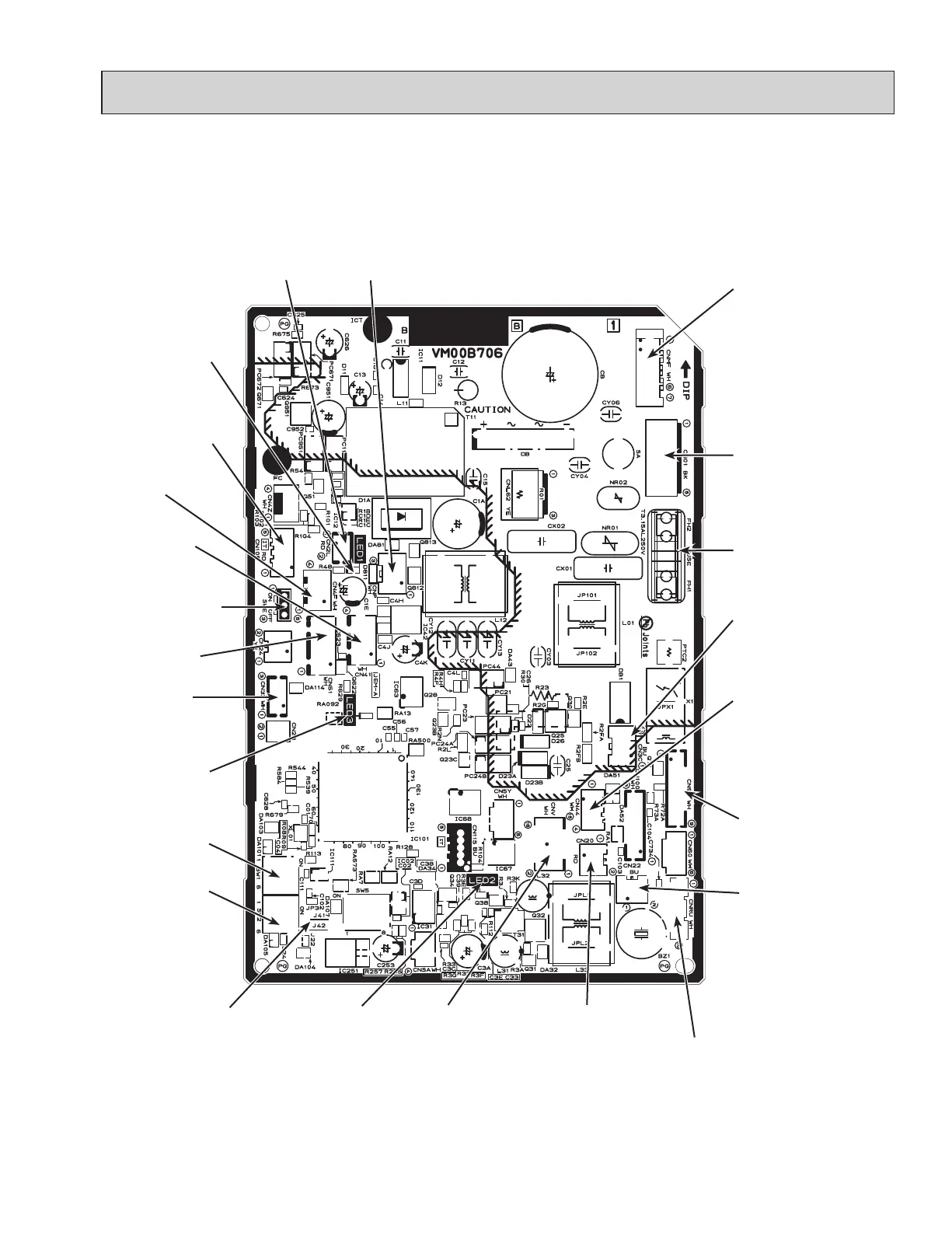
9-7. TEST POINT DIAGRAM
Indoor controller board
TPKA0A0241KA80A TPKA0A0301KA80A TPKA0A0361KA80A
CN44
Pipe temperature thermistor
1–2 : Liquid (TH2)
3–4 :
Condenser/Evaporator
(TH5)
CN20
Room temp.
thermistor (TH1)
CN90
Connector to the remote
operation adapter
CNMF
Connect to the
fan motor (MF)
1–3 : 294–325 V DC
4–3 : 15 V DC
5–3 : 0–6.5 V DC
6–3 : 0 V
or 15 V DC
FUSE
(3.15 A, 250 V)
SWE
Emergency
operation connector
SW1
Model selection
SW2
Capacity setting
LED1: Power
supply (I.B)
Jumper wire J41,J42
Pair No. setting for
wireless remote controller
CN01
Connect to the
Terminal block (TB4)
1–3 : 208/230 V AC
CNRU
Connect to SWITCH BOARD (S.B),
LED BOARD (L.B), and PCB for
WIRELESS REMOTE CONTROLLER
(option)
CN3C
Transmission
(Indoor/outdoor)
(0–24 V DC)
CN22
Connect to the terminal
block (TB5) (Remote
controller connecting
wire)
LED2: Power
supply (Wired
remote controller)
LED3: Transmission
(Indoor/Outdoor)
CN4F
Float switch (FS)
(option)
CN41
Connector
(HA terminal-A)
CNV
Vane motor
(MV1, MV2)
12 VDC pulse outlet
CN32
Remote switch
CN2L
Connector
(LOSSNAY)
CNP Drain pump output
1-3: 13 VDC
(option)
CN105
IT Terminal
CN51
Centrally control
 Loading...